Step-by-Step Guide to Flame Sensor with Buzzer Using Arduino
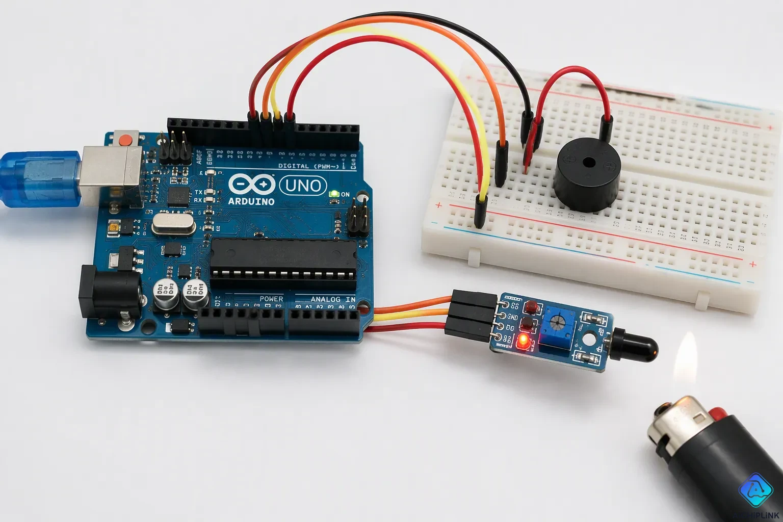
A flame sensor with buzzer is a simple Arduino fire-detection alarm. It beeps and lights an LED the moment it senses a flame. You will build one from scratch, step by step, even with zero Arduino experience. This tutorial is beginner-friendly and low-cost. You only need an Arduino UNO, a flame sensor module, and a piezo buzzer. The sensor reads infrared light from a flame and sends a signal to the board. Your alarm then responds fast. Working smoke alarms matter: the NFPA reports that three out of five home fire deaths from 2007–2011 happened in properties without working alarms. A buzzer and a LED give you a cheap early warning.
Key Takeaways
-
Build a low-cost fire alarm with an Arduino UNO, flame sensor, and buzzer.
-
Wire the sensor to digital pin 7, buzzer to pin 8, and LED to pin 9.
-
Upload a simple code that reads the sensor and triggers the alarm.
-
Test with a lighter and adjust the potentiometer for sensitivity.
-
Expand the project with gas sensors or Wi-Fi alerts for more safety.
Components for the Flame Sensor with Buzzer
Required Parts List
Collect these parts before you begin. The table below shows everything you need for this flame sensor with buzzer build. Most of these items are found in common Arduino starter kits, so the total cost stays low.
| Part | Purpose |
|---|---|
| Arduino UNO | Reads the sensor signal and controls the outputs |
| Flame sensor module (HW-072) | Detects infrared light from a fire |
| Piezo buzzer | Makes the warning sound |
| LED (with resistor) | Gives a visual warning |
| Breadboard | Holds connections without soldering |
| Jumper wires | Carry power and signals |
| Lighter | Tests the build safely |
The HW-072 flame sensor module is a common, low-cost choice. It runs on 3.3V or 5V, so it works directly with your board. Its detection range is about 30 cm to 80 cm (12–32 inches) under normal indoor lighting. The viewing angle sits around 60 to 120 degrees, and it responds to infrared light between 760 nm and 1100 nm. An onboard potentiometer lets you adjust the threshold. A green LED shows power, and a red LED lights up on detection.
How the Flame Sensor Works
A fire gives off infrared light as it burns. The module uses an IR receiver (a photodiode) to catch that light. An operational amplifier then watches the voltage change across the receiver. When the infrared radiation passes the threshold you set with the potentiometer, the module decides a flame is present.
The flame sensor sends two outputs to your Arduino. The digital pin (DO) goes LOW (0V) when it sees a flame and HIGH (5V) when it does not. The analog pin (AO) gives a voltage that moves inversely with infrared intensity — a bigger fire means lower voltage. For a simple buzzer alarm, the digital output is the easiest to use. Your code just checks for LOW. If you later want to measure fire strength, the analog pin is there for you. This part is not an arduino ldr module, which senses visible light instead.
Wiring the Flame Sensor and Buzzer
Circuit Schematic Overview
Grab your breadboard and push the flame sensor module into it. The module has three pins, and each one has a clear job. VCC takes power, GND goes to ground, and OUT carries the signal. A quick look at the module pinout helps you plan the wiring before you touch a single wire.
| Pin | Function |
|---|---|
| OUT | Analog output signal |
| VCC | Module power supply (5V) |
| GND | Ground |
Now picture the full circuit diagram in your head. Run the sensor VCC pin to the 5V rail on your Arduino. Connect sensor GND to the Arduino GND rail. Take the OUT pin and send it to digital pin 7. That single wire carries the flame signal your code will read.
Next come the outputs. Place the buzzer on the breadboard with its positive leg on digital pin 8 and its negative leg on GND. Add the LED with its resistor on digital pin 9, then tie the other end to GND. This simple layout keeps the led and buzzer pins separate, so each part gets its own control signal. The connecting diagram of the project stays clean when you group power wires on one side and signal wires on the other.
Connection Table
Use this table as your checklist. It lists every pin, the matching Arduino pin, and a wire color suggestion to keep things tidy. Follow it row by row, and your alarm will work on the first try.
| Component Pin | Arduino Pin | Wire Color Suggestion |
|---|---|---|
| Flame sensor VCC | 5V | Red |
| Flame sensor GND | GND | Black |
| Flame sensor OUT | Digital 7 | Yellow |
| Buzzer positive | Digital 8 | Blue |
| Buzzer negative | GND | Black |
| LED anode (through resistor) | Digital 9 | Green |
| LED cathode | GND | Black |
Double-check the led and buzzer pins before you power up. A swapped positive and negative leg on the buzzer will silence it, and a backward LED simply will not light. The wiring / connections above match the code in the next section, so keep the pin numbers handy. Once the flame sensor with buzzer is wired this way, the sensor watches for fire and the buzzer and LED wait for their cue. Your alarm is now one upload away from working.
Arduino Code Logic
What Happens When the Flame Sensor Detects a Flame
The flame sensor detects a flame by watching its digital output pin. That pin sits at HIGH when the air is clear. The moment infrared light from a fire crosses the set point, the pin drops to LOW. Your sketch reads that change and reacts.
Think of it as a simple switch with two states. A LOW reading means fire. A HIGH reading means all clear. You do not need to measure anything fancy for a basic alarm. Just check which state the pin reports.
The sensor also has an analog output. It gives you a number between 0 and 1023, much like the analog value from the ldr in a light-sensing project. That reading helps when you want to judge how close the flame is. For this build, the digital pin does the job.
Step-by-Step Code Logic
Here is the logic your sketch follows, in plain steps:
-
Define the pin numbers at the top. Name the sensor pin, the buzzer pin, and the LED pin so the code stays readable.
-
In
setup(), set the buzzer pin as OUTPUT withpinMode(BUZZER_PIN, OUTPUT). Do the same for the LED pin, and set the sensor pin as INPUT. -
In
loop(), the flame sensor is read withdigitalRead(). Store the result in a variable. -
Compare that reading against your condition. A LOW result means fire is present.
-
When fire shows up, turn on the LED and buzzer. Send HIGH to both pins.
-
When the reading returns to HIGH, turn off the LED and buzzer.
The sensor value arrives as a simple HIGH or LOW, so the check stays short. You can also add a serial print to watch the readings while you test. Adjust the onboard potentiometer to set the threshold that suits your room.
Arduino IDE Setup and Complete Code
Installing the IDE and Board Drivers
First, install arduino ide on your computer. Head to the Arduino download page and grab the latest arduino ide software. On Windows, skip the app store version — automatic updates there can introduce bugs. Download the ZIP file, extract it, and run the executable inside the folder. On macOS, the download unzips itself, usually into Downloads. Keep it there or drag it into Applications.
Windows needs a driver step. Plug in your board and wait. The automatic install will likely fail. Open Device Manager, look under Ports (COM & LPT) for "Arduino UNO (COMxx)", and right-click it. Choose Update Driver Software, then Browse my computer. Point it to the drivers folder inside your arduino ide software directory and select Arduino.inf. Finish the install and note the COM number. macOS needs no drivers at all — skip straight ahead. If you ever switch to an arduino leonardo, remember it enumerates differently, so recheck the port.
Uploading and Testing the Sketch
Now open the IDE and reconnect the board. Select Tools > Board > Arduino Uno, then Tools > Port and pick your COM number. Unplug and replug the cable if you cannot tell which port is yours. Paste this complete sketch, which matches the wiring from earlier:
const int SENSOR_PIN = 7;
const int BUZZER_PIN = 8;
const int LED_PIN = 9;

void setup() {
  pinMode(SENSOR_PIN, INPUT);
  pinMode(BUZZER_PIN, OUTPUT);
  pinMode(LED_PIN, OUTPUT);
}

void loop() {
  int sensor value = digitalRead(SENSOR_PIN);
  bool fire = (sensor value == LOW);
  digitalWrite(LED_PIN, fire);
  digitalWrite(BUZZER_PIN, fire);
  delay(100);
}
Press Upload and wait for "Done Uploading". If the board rejects the upload, the port is usually wrong. This tutorial keeps the sketch short on purpose, so you can read every line.
Testing time. Light a lighter and hold it about 15 cm from the sensor. Keep your fingers clear of the flame. The led and buzzer should react within a moment. Pull the lighter away and watch them stop. If nothing happens, turn the potentiometer screw slowly until the module's red LED triggers. That sets your threshold. Watch the sensor value in the Serial Monitor if you add a print line — it shows HIGH and LOW flipping as the flame comes and goes. Your alarm is now live.
How the Fire Alarm Works
Detection and Alarm Flow
The flow is short and easy to follow. Your flame sensor detects a flame, the Arduino reads the signal, the buzzer sounds, and the LED lights up. This chain repeats again and again inside loop(), so the alarm keeps watching all the time.
Timing matters here. A detector can pick up a flame almost instantly, often within milliseconds. Many modules then hold the output for a short delay before the alarm goes off. That pause cuts down on false triggers from sunlight, lightning, or welding sparks.
| Stage | Timing |
|---|---|
| UV detection of fire or explosion | 3–4 milliseconds |
| Added delay before alarm (to reduce false alarms) | 2–3 seconds |
Your build reads a digital pin, so the reaction feels immediate once the module's output flips. Watch the sensor value on the Serial Monitor during testing. You will see it switch as the flame appears and disappears.
Practical Fire Alarm Applications
This little fire alarm fits more places than you might think. You can mount it in a kitchen, bedroom, or living room to catch early fire signs. Small shops and offices use it too, especially where a commercial system costs too much. Students also build it for science fairs, since it teaches digital sensors, logic, and alerts in one project.
This Arduino-based fire alarm is a low-cost, easy-to-build, effective solution for detecting early fire signs using flame and temperature sensors. It shows how sensors work for real-world safety, basic Arduino programming and logic control, and real-time alerts through a buzzer and LED.
Want to cover more area? Add an MQ2 gas sensor. Wire both modules to the same board, read each one in real time, and set a limit for each. If either sensor goes past its limit, the warning goes off. An OLED screen can show gas levels, and an ESP8266 module can send alerts to your phone. That turns a simple flame sensor with buzzer into a fuller safety system. One note: this project is not an arduino ldr module, which reacts to visible light rather than infrared.
You built a working flame sensor with buzzer alarm using Arduino. Test it safely: hold a lighter at a distance and watch the led and buzzer respond. Then turn the onboard preset potentiometer to adjust the threshold for your room.
Your flame sensor is ready for upgrades. Try these next steps:
-
Add a relay to trigger a water pump, fan, or siren.
-
Add an LCD display to show real-time readings.
-
Add Wi-Fi or GSM alerts for remote notification.
Each upgrade turns your simple fire alarm into a stronger safety tool. Keep testing, keep tuning, and enjoy watching your flame detection project grow.

Written by Jack Elliott from AIChipLink.
AIChipLink, one of the fastest-growing global independent electronic components distributors in the world, offers millions of products from thousands of manufacturers, and many of our in-stock parts is available to ship same day.
We mainly source and distribute integrated circuit (IC) products of brands such as Broadcom, Microchip, Texas Instruments, Infineon, NXP, Analog Devices, Qualcomm, Intel, etc., which are widely used in communication & network, telecom, industrial control, new energy and automotive electronics.
Empowered by AI, Linked to the Future. Get started on AIChipLink and submit your RFQ online today!
Frequently Asked Questions
How do I adjust the sensitivity of my flame sensor?
Turn the small screw on the module's potentiometer. Watch the red LED while you move a lighter closer and farther away. Stop when the module triggers at the distance you want. Test again after each small turn, since the setting is fine.
Why does my buzzer stay silent when a flame appears?
Check the buzzer's positive leg first. It must sit on digital pin 8, and the negative leg goes to GND. A backward buzzer makes no sound. Also confirm your sketch uploaded correctly and the sensor pin reads LOW near a flame.
Can I use an Arduino Leonardo instead of the UNO?
Yes. The wiring and code stay the same. One thing changes: the arduino leonardo shows up on a different port, so pick the right one under Tools > Port. Recheck the port after you plug the board in.
What causes false triggers from my alarm?
Sunlight, welding sparks, and strong lamps can fool the sensor. Lower the sensitivity with the potentiometer. Keep the module away from direct sun and bright bulbs. A short delay in your code also helps filter out brief flashes.
How close must the flame be for detection?
The HW-072 module typically detects a flame from about 30 cm to 80 cm (12–32 inches) indoors. Your threshold setting changes that range. Move the lighter closer if nothing happens, then tune the potentiometer for your room.