 In the world of analog electronics, a single transistor is rarely enough. To get a weak signal (like from a microphone) strong enough to drive a speaker, you need to connect multiple amplifiers in a chain.
The most popular, cost-effective, and reliable way to connect these stages is the RC Coupled Amplifier.
Using simple Resistors (R) and Capacitors (C), this circuit is the backbone of almost every audio system, radio, and TV ever built. This guide breaks down how it works, why the capacitor is so critical, and the physics behind its performance.
1. What is an RC Coupled Amplifier?
An RC Coupled Amplifier is a multi-stage amplifier circuit where the output of the first stage is connected to the input of the second stage through a Coupling Capacitor ($C_C$) and a Resistor.
It is primarily used for Voltage Amplification. Because resistors and capacitors are cheap and tiny, this configuration allows engineers to build lightweight, compact circuits without bulky iron-core transformers.
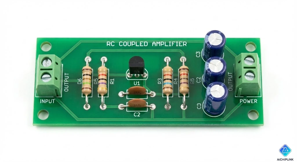
2. Circuit Diagram & Construction
To understand the working, let's look at a standard two-stage Common Emitter (CE) amplifier chain.
Key Components:
- Transistors ($Q_1, Q_2$): The active engines. Usually NPN BJTs configured in Common Emitter mode for high gain.
- Biasing Resistors ($R_1, R_2, R_E$): These form a voltage divider to set the stable operating point (Q-point) of the transistor.
- Collector Resistor ($R_C$): The load resistor across which the amplified voltage drops.
- Coupling Capacitor ($C_C$): The Critical Link. It connects the collector of $Q_1$ to the base of $Q_2$.
- Bypass Capacitor ($C_E$): Connected in parallel to the emitter resistor to provide a low-resistance path for AC signals, preventing negative feedback (gain loss).
3. Working Principle
How does the signal travel from start to finish?
- Input: A weak AC signal is applied to the base of Transistor $Q_1$.
- Amplification (Stage 1): $Q_1$ amplifies the signal and inverts it ($180^\circ$ phase shift). The amplified signal appears across the collector resistor $R_C$.
- Coupling: The output of Stage 1 contains both the AC signal (audio) and a high DC voltage (bias).
- If we connected this directly to the next transistor, the high DC voltage would flood the base of $Q_2$, driving it into saturation and ruining the circuit.
- The Coupling Capacitor ($C_C$) solves this. It blocks the DC component but allows the AC signal to pass through to the base of $Q_2$.
- Amplification (Stage 2): $Q_2$ takes this clean AC signal, amplifies it further, and sends it to the output.
Total Gain ($A$): The total gain is the product of the individual stage gains: $$A_{total} = A_1 \times A_2$$
4. Frequency Response Characteristics
One of the defining features of an RC Coupled Amplifier is its Frequency Response Curve. It looks like a "hill" or a "bell curve."
It is divided into three regions:
1. Low Frequency Range (< 50 Hz)
- Performance: Gain drops significantly.
- Reason: Capacitive Reactance ($X_C = \frac{1}{2\pi fC}$). At low frequencies ($f$), the reactance of the coupling capacitor is extremely high. It acts like a resistor, blocking some of the signal from reaching the next stage.
2. Mid-Frequency Range (50 Hz - 20 kHz)
- Performance: Constant, Maximum Gain.
- Reason: The capacitor's reactance is low enough to be negligible, acting like a short circuit for the AC signal. Ideally, this range covers the entire human hearing spectrum, which is why it's great for audio.
3. High Frequency Range (> 20 kHz)
- Performance: Gain drops again.
- Reason: Parasitic Capacitance. At high frequencies, the internal capacitance of the transistor and the stray capacitance of the wiring act like short circuits to the ground, bypassing the signal before it can be amplified.
5. Advantages vs. Disadvantages
| Advantages | Disadvantages |
|---|---|
| Excellent Audio Fidelity: Flat gain across the audible range. | Poor Impedance Matching: Cannot drive low-impedance loads (like speakers) directly without a final power stage. |
| Low Cost: Resistors and capacitors are the cheapest electronic components. | Low Power Efficiency: Resistors dissipate heat ($I^2R$ loss), making it bad for high-power applications. |
| Compact: No heavy, bulky transformers required. | Moisture Sensitivity: Old capacitors can degrade over time in humid environments. |
6. Applications
Where will you find this circuit?
- Audio Preamplifiers: Boosting the millivolt signal from a microphone or electric guitar pickup to a level that a power amplifier can use.
- Radio & TV Receivers: Used in the initial stages of signal processing to amplify weak incoming radio waves.
- Public Address (PA) Systems: The voltage amplification stages before the final power output.
7. Conclusion
The RC Coupled Amplifier is the workhorse of signal processing. While it may not have the raw power of a transformer-coupled amp or the DC precision of a direct-coupled amp, its balance of low cost, small size, and excellent frequency response makes it the standard choice for 90% of voltage amplification tasks.
Sourcing Amplifier Components? Building your own pre-amp or repairing an old radio? Visit Aichiplink.com to find high-quality Audio Transistors, Film Capacitors, and Metal Film Resistors for your next project.

Written by Jack Elliott from AIChipLink.
AIChipLink, one of the fastest-growing global independent electronic components distributors in the world, offers millions of products from thousands of manufacturers, and many of our in-stock parts is available to ship same day.
We mainly source and distribute integrated circuit (IC) products of brands such as Broadcom, Microchip, Texas Instruments, Infineon, NXP, Analog Devices, Qualcomm, Intel, etc., which are widely used in communication & network, telecom, industrial control, new energy and automotive electronics.
Empowered by AI, Linked to the Future. Get started on AIChipLink.com and submit your RFQ online today!
Frequently Asked Questions
What is an RC coupled amplifier used for?
It is mainly used for voltage amplification, especially in audio preamplifiers and signal processing stages.
Why is a coupling capacitor used in RC amplifiers?
The coupling capacitor blocks DC bias voltage while allowing the AC signal to pass between amplifier stages.
What is the main advantage of an RC coupled amplifier?
It offers low cost, compact size, and a flat frequency response across the audio range.
Why does gain drop at low and high frequencies?
At low frequencies, capacitor reactance is high; at high frequencies, parasitic capacitances reduce gain.
Can an RC coupled amplifier drive a speaker directly?
No. It has poor impedance matching and usually requires a power amplifier stage to drive speakers.