Interface AD9850 DDS Signal Generator Module with Arduino A Complete Tutorial
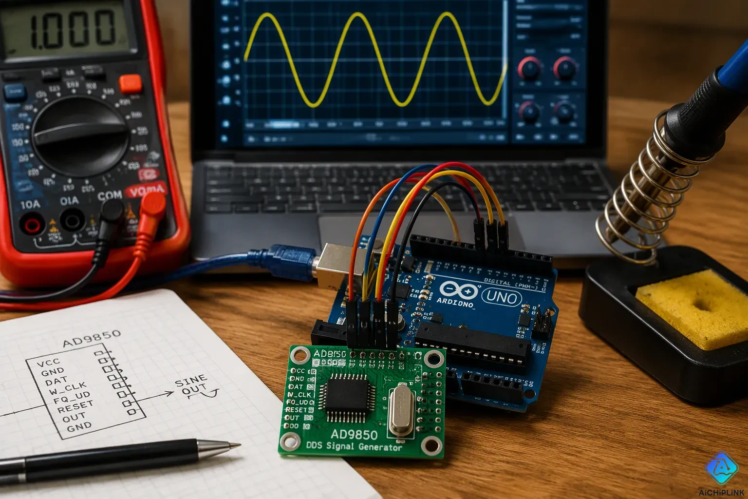
You can connect the Interface AD9850 DDS Signal Generator Module to an Arduino with just a few jumper wires and one library. The board starts making sine and square waves as soon as your sketch runs. No hard setup stands between you and a working signal source.
This guide gives you the full path: correct wiring, the library installed, working code, and a checked waveform at the output. You will also see the pinout and key specs for the Interface AD9850 DDS Signal Generator Module. Each step stays short and practical, so you can build the circuit and test it in one sitting. The Arduino acts as the microcontroller that sets the output frequency.
Key Takeaways
-
Connect the AD9850 module to your Arduino with just a few jumper wires and one library.
-
Wire the four control pins correctly: W_CLK to pin 8, FQ_UD to pin 9, DATA to pin 10, and RST to pin 11.
-
Install the AD9850 library from GitHub and restart the Arduino IDE to make it available.
-
Upload a simple sketch to set a frequency and generate sine or square waves.
-
Test the output with an oscilloscope or counter to confirm a steady waveform.
What Is the DDS Signal Generator Module?
The dds signal generator module is a small board that makes clean waveforms when a microcontroller like an Arduino controls it. You send it a tuning command, and it creates a sine or square wave at the level you choose. The board does the waveform math, so your sketch only has to set the output frequency. A second dds signal generator module on your bench lets you compare two signals side by side.
How Direct Digital Synthesis Works
A direct digital synthesizer makes a waveform by stepping through a stored table of sample values at a steady clock rate. The table holds one full cycle of the wave. Each step moves a phase accumulator forward, and the accumulator value points to the next sample in the table. A faster step rate makes a higher tone, and a slower rate lowers the frequency.
The AD9850 takes its tuning command as a 40-bit serial data word. You can load this word in parallel or serial form, and most Arduino builds use serial mode because it needs fewer pins. The chip then turns the digital samples into an analog wave. This design gives you fast, precise frequency changes without analog adjustment parts.
Key Features and Specifications
The board offers two output types: a sine wave and a square wave. You control both from the same command, and the square output works well for clock and pulse testing. The module runs from a 3.3 V to 6 V supply, which matches the Arduino logic level. You can also feed the output into a scope or a counter for a quick check.
| Feature | Detail |
|---|---|
| Waveform outputs | Sine and square |
| Control interface | Serial data word |
| Logic supply | 3.3 V to 6 V |
| Host control | Arduino or other microcontroller |
The direct digital synthesizer signal generator works for bench testing, signal injection, and sweep experiments. Its serial interface keeps wiring simple, and the onboard output pins connect straight to your test point.
AD9850 Pinout and Configuration
Module Pin Descriptions
The ad9850 pinout is simple once you group the pins by job. Power enters at VCC, and the board accepts 3.3 V to 6 V. Ground returns through GND. The module also carries eight parallel data lines, labeled D0 through D7. You will not use all of them in serial mode.
Four control pins run the communication. The word load clock pin shifts each bit into the chip. The frequency update pin latches the new setting on a rising edge. The data input pin carries your serial bits through D7. The master reset pin clears the registers and sets the output to a known state.
The output side gives you two pairs. Sine-Wave 1 and 2 are the DAC current outputs. Square-Wave 1 and 2 are complementary outputs. This pinout description covers every connection you need for a basic build.
Arduino Pin Configuration Table
This pin configuration table maps the module to an Arduino Uno. Wire the control lines to digital pins 8 through 11. Keep the power and ground links short.
| Module Pin | Arduino Pin |
|---|---|
| VCC | 5V |
| GND | GND |
| W_CLK | Digital 8 |
| FQ_UD | Digital 9 |
| DATA | Digital 10 |
| RST | Digital 11 |
The pin configuration above works with most serial-mode sketches. Check your library's example code first, because some sketches expect a different order. A wrong pin configuration will leave the output silent.
The board runs an oscillator at 125 MHz and can produce output from 0 to 40 MHz. It operates from -40 to 85 °C. Treat the data and the reset pins with care during wiring, and confirm each connection before you apply power.
Interfacing the AD9850 DDS Signal Generator Module with Arduino
Required Components
You need only a handful of parts to start interfacing the AD9850 DDS signal generator module with your Arduino. Gather an Arduino board, the AD9850 module, jumper wires, a breadboard, and a USB cable. The Arduino Nano works well here, and any Uno-style board follows the same steps. The USB cable carries power and lets you upload your sketch. The breadboard holds the module steady while you test the connections.
Four control signals form the heart of the interface. The word clock shifts serial bits into the chip. The frequency update line latches each new setting. The data line carries the tuning word. The reset line clears the registers at startup. Your sketch configures these four pins as outputs in setup and toggles them inside the reset and update routines. That pattern confirms the four control lines are the essential interface signals between the microcontroller and the module.
Step-by-Step Wiring Guide
Work through these steps in order. Power down the Arduino before you touch any wire.
-
Connect Arduino 5V to the module's VCC pin. This link feeds the board first.
-
Connect Arduino GND to the module's GND pin. A shared ground keeps every signal stable.
-
Wire W_CLK to digital pin 8.
-
Wire FQ_UD to digital pin 9.
-
Wire DATA to digital pin 10.
-
Wire RST to digital pin 11.
Double-check each connection against your library's example sketch before you apply power. Pin order varies between libraries, and a mismatched line leaves the output silent.
Some published schematics use a different mapping. One common table lists W_CLK on D13, FQ_UD on D8, Data on D10, and Reset on D9. The matching code sets W_CLK_PIN to 13, FQ_UD_PIN to 8, and RESET_PIN to 9. Either layout works when your sketch agrees with your wiring.
A reader reports that the DATA pin needed Arduino D11 rather than D10, citing comments in the library's .cpp file. Their Uno only produced output after that change.
Treat any schematic diagram as a starting point, not a rule. Verify the pin constants in your sketch, then match your wires to them. Good connections matter more than the exact pin numbers.
Once the wiring is complete, load a simple single-frequency test script. Set one output frequency, upload the sketch, and watch the sine output on a scope or counter. A steady wave confirms the interface ad9850 dds signal generator module is working. If you see nothing, recheck the four control lines first. Most failures trace back to a loose wire or a swapped data line. With a clean signal in hand, you can move on to library setup and richer code.
Library Setup and Arduino Code
Installing the AD9850 Library
The Arduino IDE gives you two ways to add a library. The Library Manager route works for many boards, but the AD9850 library often installs best from its GitHub source. Follow these steps to place it in your sketchbook.
-
Open the AD9850 GitHub repository and download the ZIP archive to a folder you can find again.
-
Unzip the file. You get a folder whose name usually includes the branch, typically AD9850-master.
-
Rename that folder to AD9850.
-
Copy the renamed folder into the libraries directory inside your Arduino sketchbook.
Restart the Arduino IDE after the copy. The IDE scans the libraries folder at startup, so a restart makes the new library show up under Sketch > Include Library. If the library does not appear, check the folder name first. A nested folder such as AD9850/AD9850 breaks the scan.
Example Sketch with Line-by-Line Explanation
The sketch below sets one output frequency and holds it. Read the comments as you go, because each line has a job.
#include <AD9850.h>                 // load the library
const int W_CLK = 8;                // word clock pin
const int FQ_UD = 9;                // frequency update pin
const int DATA  = 10;               // serial data pin
const int RST   = 11;               // master reset pin
AD9850 dds(W_CLK, FQ_UD, DATA, RST); // create the device object
void setup() {
  dds.begin();                      // start the interface
  dds.setFrequency(1000);           // 1 kHz output
}
void loop() {
}
The include line pulls the library into your arduino code. The four pin constants must match your wiring, so change them if your board differs. The constructor hands those pins to the library object. Inside setup, begin starts the interface ad9850 dds signal generator module, and setFrequency writes the tuning word that sets the output frequency. The empty loop leaves the wave running without further commands.
The library exposes a few functions worth knowing. setFrequency is the core method for setting the output frequency. begin initializes the device and must run after SPI.begin in recent versions. Constructors added in version 0.7.2 no longer need the spiClock line. The maximum sine output reaches 40 MHz, and phase steps run in units of 11.25 degrees. Your microcontroller sends each command over the serial link, and the frequency update pin latches it on a rising edge.
Upload the sketch and probe the sine output. A steady tone confirms your arduino code and wiring agree. If the output stays flat, recheck the pin constants against your wires before you change anything else.
Alternative Modules and Applications
Comparing Alternative DDS Modules
The AD9850 is one option among several DDS chips you can pair with an Arduino. Each alternative brings its own strengths, and the right pick depends on your project goals. A fair comparison helps you match the board to the job at hand.
| Module | Strength | Best Fit |
|---|---|---|
| AD9833 | Compact board with a simple serial interface | Small builds with limited space |
| AD9851 | Higher internal clock rate than the AD9850 | Projects that need faster output |
| Si5351 | Multiple clock outputs from one chip | Clock-based projects and multi-signal setups |
The AD9833 suits tight layouts where board space matters most. Its small footprint leaves room for other parts on a crowded breadboard. The AD9851 targets builds that push for faster waveform output, and it keeps the same serial control style. The Si5351 shines when you need several clock lines at once. None of these boards replaces the others outright. Your choice comes down to size, speed, and output count. Check the library support for each chip before you commit, because a well-documented library saves hours of setup time.
Where the AD9850 Fits Best
The dds signal generator module works well as a compact, low-cost source for small-signal generation. You can watch its sine or square output on an oscilloscope and confirm the result right away. The board also serves communication systems, clock-based projects, and analog-to-digital converter work. A microcontroller sends each tuning command, so your sketch keeps full control of the output. Bench testing and signal injection round out its common uses. The serial interface keeps the wiring light, so you can move the board between projects without a rebuild.
A pulse generator with a frequency sweep shows the board's range. Follow this pattern:
-
Start the sweep at 1 Hz.
-
Raise the output by 0.5 Hz every second.
-
Stop the climb at 10 Hz.
You set the start point, end point, step size, and step interval yourself. The output can be a square wave or a sine wave. This sweep test gives you a quick way to check a circuit across a range of tones. Try a slow sweep first, then tighten the step size once you trust the setup. The same pattern works for filter tests and response checks.
You now have a working signal source on your bench. You wired the module, installed the library, and uploaded code that makes sine and square waves. Each step built on the last one, and a steady output on your scope proves it works.
The interface ad9850 dds signal generator module gives hobbyists an easy, low-cost way to get started with DDS signal generation. Your microcontroller handles the tuning commands, so the dds signal generator module is simple to control.
Share your projects or questions in the comments below. As a next step, try a frequency sweep and watch the output change across a range of tones.

Written by Jack Elliott from AIChipLink.
AIChipLink, one of the fastest-growing global independent electronic components distributors in the world, offers millions of products from thousands of manufacturers, and many of our in-stock parts is available to ship same day.
We mainly source and distribute integrated circuit (IC) products of brands such as Broadcom, Microchip, Texas Instruments, Infineon, NXP, Analog Devices, Qualcomm, Intel, etc., which are widely used in communication & network, telecom, industrial control, new energy and automotive electronics.
Empowered by AI, Linked to the Future. Get started on AIChipLink and submit your RFQ online today!
Frequently Asked Questions
Why does my AD9850 module show no output after wiring?
Check the four control lines first. A loose wire or a swapped data line causes most failures. Confirm your sketch's pin constants match your actual wiring. Some sketches expect a different order than the table above. Also verify the library folder sits directly inside your sketchbook's libraries directory, not nested one level deeper.
Can I run the module from a 3.3V board?
Yes. The module accepts 3.3 V to 6 V at VCC, so a 3.3V board can power it. Keep in mind the logic level of your control signals. Match your sketch and wiring to your board's voltage before you apply power.
Which pins should I use on an Arduino Uno?
Digital pins 8 through 11 handle the four control signals in the common serial-mode layout. Wire W_CLK to pin 8, FQ_UD to pin 9, DATA to pin 10, and RST to pin 11. Connect VCC to 5V and GND to GND. Always confirm the pin constants in your library's example sketch first.
What is the maximum output frequency?
The board runs an oscillator at 125 MHz and produces output from 0 to 40 MHz. The maximum sine output reaches 40 MHz. Phase steps run in units of 11.25 degrees. Start with a low frequency for your first test, then raise it once you confirm a steady wave.
Can I generate a frequency sweep with this module?
Yes. Your sketch sets the start point, end point, step size, and step interval. A simple pattern starts at 1 Hz, raises the output by 0.5 Hz every second, and stops at 10 Hz. The output can be a square wave or a sine wave. Try a slow sweep first.