How to Build a Capacitor ESR Meter Using an Oscilloscope
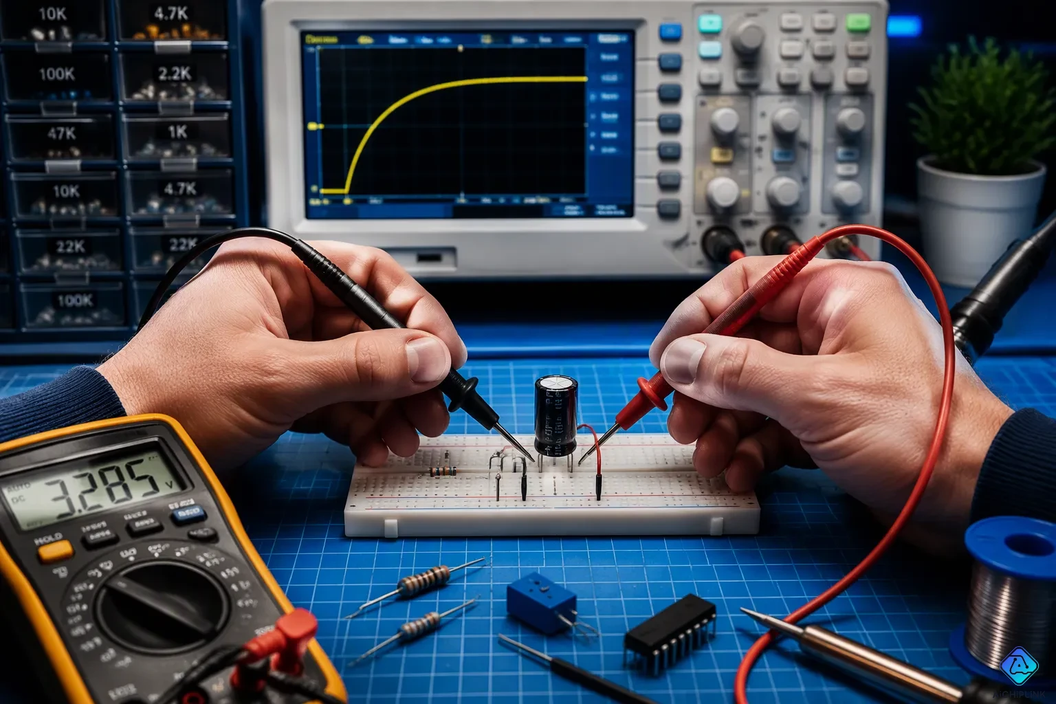
A bad electrolytic capacitor often looks perfectly fine. The can is whole, the top is flat, and a standard multimeter shows a normal capacitance value. But the part has high ESR, and it will fail in the circuit. A multimeter cannot measure that internal resistance.
You can fix this problem with a basic oscilloscope and a few cheap parts. A 555 timer circuit is the heart of a working capacitor ESR meter. The ESR scope method needs no costly bench equipment. Build an oscilloscope ESR tester in an afternoon for very little money. The ESR meter you put together will find bad parts fast, and each measurement teaches you real ESR theory.
Key Takeaways
-
ESR shows how healthy a capacitor is better than capacitance by itself.
-
Make a low-cost ESR meter using a 555 timer and an oscilloscope.
-
Use two scope probes and a simple formula to find ESR.
-
Use a resistor with a known value to calibrate it, so your readings are accurate.
-
Test the capacitor out of the circuit for the best results; in-circuit checks are rough.
ESR Basics and Why It Matters
What ESR Really Is
Every capacitor has a small equivalent series resistance inside its case. This internal resistance comes from the electrolyte, the foil, and the internal connections. In a healthy part it stays very low. As an electrolytic capacitor ages, its liquid electrolyte escapes through vaporization and diffusion. The loss of conductive material shrinks the effective contact area inside the part. That change raises the internal resistance of the capacitor while capacitance slowly falls.
ESR climbs first, and it climbs fast. The table below shows the trend.
| Metric | Value |
|---|---|
| ESR increase per decade of aging | approximately 2× |
| End-of-life ESR (replacement threshold) | 2–3× the initial value |
| Primary predictive-maintenance parameter | ESR (rises before capacitance drops significantly) |
Heat drives this process. Each 10°C rise roughly halves expected lifetime, and ripple current adds localized heating that compounds electrolyte evaporation. The drying rate depends on temperature, and parts exposed to higher ripple currents degrade faster. You can track the decline with a simple esr measurement, and the reading tells you more about health than a capacitance check ever will. A part at twice its initial value is aging; three times means replace it.
Why Multimeters Miss It
A standard multimeter cannot measure esr directly. The part blocks DC, so a plain ohmmeter reading is impossible. To isolate the small internal resistance, an instrument must ignore the much larger capacitive reactance. That job needs an AC test signal at a defined frequency, often around 100 kHz for electrolytic capacitors. At that frequency the measured impedance of larger capacitors approximates the part's series resistance.
In-circuit readings fail for another reason. Surrounding components provide alternative current paths that combine with the part under test. Resistance values then reflect the sum of the part plus all parallel paths. Diode mode measures junction voltage drop, which has no correlation to part health. Aged capacitors can pass every multimeter check and still fail in circuit. Reliable screening often requires removing the component or using a dedicated meter. Bench screening is also time-consuming for large batches, which motivates a dedicated build.
Building a Capacitor ESR Meter
Parts List and Typical Values
You need just a few common parts for this capacitor esr meter. The table below shows each component, a typical value, and what it does in the circuit.
| Component | Typical Value / Specification | Role in Circuit |
|---|---|---|
| 555 timer IC | Conventional astable multivibrator configuration | Generates the square wave |
| Potentiometer | 100K | Frequency tuning to minimize voltage across the capacitor |
| Output series resistor (ROUTPUT) | 47 Ω | Sets output impedance of the push-pull power stage |
| Output stage | Push-pull configuration | Provides a known output impedance for the calculation |
The esr meter circuit finds the result with a simple formula: ESR = (VCAP × ROUTPUT) / (VOUTPUT − VCAP). You measure both voltages with the scope, and the math gives you the internal resistance directly. You do not need a calibration table. The 100K potentiometer lets you tune the drive frequency until the voltage across the capacitor drops to its lowest point. That null point marks the frequency where the capacitive reactance is very low, and the remaining voltage shows the ESR alone.
555 Timer Oscillator Circuit
A 555 timer (IC1) runs as a free-running oscillator at 2.3 kHz and acts as the timebase for this esr capacitor tester circuit. The timer output becomes narrow pulses of about 7.7 µs. A NAND Schmitt trigger (IC2) and transistor Q1 send those pulses to the capacitor under test. A 100 Ω series resistor limits the current to roughly 50 mA. A 1 Ω ESR then makes about 50 mV pulses across the part. A scope with 5 mV vertical sensitivity can resolve ESR down to about 0.1 Ω or less. Transistor Q2 discharges the test capacitor during the off part of each cycle, so the average DC component stays at zero. Diodes D1 and D2 clamp the maximum output to about 0.6 V, which matches roughly 12 Ω ESR. Four AA batteries can power the circuit when accuracy is not critical.
The power stage needs care. A constant current source sets its DC operating point with resistors R2, R3, and R6, and a 9 V supply gives a Q2 emitter current near 6 mA. A 100 kHz oscillator built from Q1, Q3, L1, and C1 modulates that current source and makes the AC excitation. A self-biasing current sink around Q4 gives a DC path for the Q2 collector current. The source current splits: DC flows through Q4, and the AC part couples to the part under test. The left-hand section acts as an ideal current source with an output resistance of about 6.67 kΩ. That value is very large compared to the resistance values you measure, so a known AC current reaches the device under test.
For occasional measurements, you can skip the build. A signal generator and an oscilloscope form a bench method that works well for one-off checks. You set the generator to a fixed frequency and compare the two traces. This esr measuring device approach costs nothing extra if the gear already sits on your bench. The dedicated capacitor esr meter still wins for batch work, because it needs no setup between parts. Either way, the reading tells you the health of the capacitors in seconds.
ESR Measurement with an Oscilloscope
Setup and Measurement Procedure
You need two channels for this esr measurement. Connect the first scope probe across the 47 Ω output series resistor. Connect the second probe across the capacitor under test. Clip both ground leads to the same circuit ground point. Keep the leads short, because long ground leads pick up noise and add inductance that skews the reading.
Power the esr meter circuit and let the 555 timer settle. Adjust the 100K potentiometer until the signal across the capacitor reaches its minimum amplitude. This null point confirms that capacitive reactance is very low at the drive frequency. The remaining voltage now reflects the capacitor's esr value alone.
Read both traces on the oscilloscope screen. The first trace shows the voltage drop across the known resistor. The second trace shows the voltage across the capacitor. Note both peak values in millivolts. A clean square wave with sharp edges tells you the setup is sound. Rounded edges or heavy noise mean you should shorten the leads or check the ground connection.
Calculating ESR of Capacitor from Readings
The math for calculating esr of capacitor values follows Ohm's law in two steps. First, derive the test current. Divide the voltage across the series resistor by its resistance: current = VRESISTOR / 47 Ω. Second, divide the capacitor voltage by that current: ESR = VCAP / current. This is the same relation the esr meter circuit uses internally, and you can verify it by hand on every part.
Here is a worked example. Suppose the scope reads 50 mV across the 47 Ω resistor. The current is 0.050 V / 47 Ω, or about 1.06 mA. Now suppose the scope reads 1.06 mV across the capacitor. Divide 1.06 mV by 1.06 mA, and you get roughly 1 Ω. That part is healthy. A reading of 5 mV across the same capacitor would give about 4.7 Ω, which signals a part near or past its replacement threshold.
The oscilloscope esr tester shines here, because the screen shows the difference instantly. A good capacitor produces a tiny, flat trace. A bad capacitor produces a visibly taller waveform at the same current. You can compare a suspect part against a known-good one side by side and see the gap without doing any math. This visual check makes measuring capacitor esr fast during a repair session. For occasional bench work, a signal generator and an oscilloscope can substitute for the built circuit, and the same two-probe method applies. Either way, you now measure esr directly and trust the result.
Limitations of a DIY ESR Meter
Design Shortcomings
A DIY esr meter is a simple tool with modest accuracy. It finds parts with ESR that is way too high, and it does that job well. A standard measurement bridge or an LCR meter gives a more exact measurement and many other parameters. Your build trades that precision for speed and low cost.
Several problems deserve attention. A shorted capacitor reads as ideally low ESR, so the meter cannot catch it. ESR also changes with applied voltage and temperature, so a part may test good when cold and fail when hot. Leftover charge or live-circuit voltage can damage the meter, so discharge every part first. Large inductance between the probes makes readings meaningless, and coiled probe cords are a common cause.
Frequency dependence matters too. ESR changes with frequency, and a reading at 100 Hz is not more accurate than one at 100 kHz. The higher-frequency value is usually larger and easier to measure. For testing esr of capacitors in-circuit, accuracy is not the goal. You get a rough, order-of-magnitude check, and no instrument gives total accuracy in-circuit. For testing esr of electrolytic capacitors with real precision, measure out of circuit with a multi-frequency meter.
Tips for Accurate Readings
Calibrate before you trust the numbers. Short the probes and adjust the preset until the meter reads zero, because an offset makes every later reading wrong. Connect a known 1 Ω resistor across the probes and mark that position, then repeat with 2 Ω and 5 Ω parts. A known-good capacitor with low ESR also works as a reference, and only the resistor value needs to be known.
Keep leads short, since probe and fixture resistance is the top error source below 1 ohm. Discharge each capacitor fully, and measure at room temperature. Match the test frequency to the datasheet value or the frequency where the part actually runs. When you test esr on a suspect part, compare it against a known-good one. This esr scope habit turns a rough number into a confident verdict.
You now have a working capacitor esr meter on your bench. It costs about $20 in parts, and it matches commercial units for spotting bad electrolytics. Around 20% accuracy is fine here, because esr is a much better health indicator than capacitance alone. The tool is simple, cheap, and good enough for repair work.
Calibrate carefully with a known resistor before you trust any reading. Practice on known-good and known-bad capacitors until the traces look familiar. This build teaches you how internal resistance rises in a failing capacitor, and it sharpens your oscilloscope skills at the same time.

Written by Jack Elliott from AIChipLink.
AIChipLink, one of the fastest-growing global independent electronic components distributors in the world, offers millions of products from thousands of manufacturers, and many of our in-stock parts is available to ship same day.
We mainly source and distribute integrated circuit (IC) products of brands such as Broadcom, Microchip, Texas Instruments, Infineon, NXP, Analog Devices, Qualcomm, Intel, etc., which are widely used in communication & network, telecom, industrial control, new energy and automotive electronics.
Empowered by AI, Linked to the Future. Get started on AIChipLink and submit your RFQ online today!
Frequently Asked Questions
What oscilloscope specs do I need for this build?
You need two channels and a vertical sensitivity of at least 5 mV per division. That sensitivity lets you see small voltage drops across the capacitor you are testing. A basic analog or digital scope works fine. Bandwidth matters little here, because the 555 timer runs at only 2.3 kHz.
Why must I adjust the potentiometer before reading?
The 100K potentiometer tunes the drive frequency until the voltage across the capacitor hits its lowest point. At that null point, capacitive reactance is very low, so the remaining voltage shows the esr alone. Skip this step and your reading mixes reactance with resistance, which makes the result too high.
Can I test capacitors while they stay in circuit?
In-circuit testing gives only a rough check. Nearby components create parallel paths that combine with the part you are testing, so the reading shows more than the capacitor itself. For a confident verdict, remove the part or compare it against a known-good capacitor of the same type.
How do I know my meter reads correctly?
Calibrate with a known resistor first. Connect a 1 Ω resistor across the probes and confirm the calculated value matches. Repeat with 2 Ω and 5 Ω parts. Then practice on known-good and known-bad capacitors until the traces look familiar. Around 20% accuracy is normal and enough for spotting bad electrolytics.