What Is an Instrument Transformer
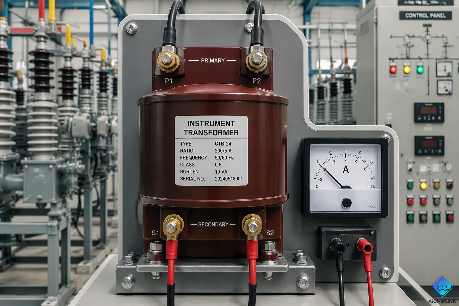
An instrument transformer is a very accurate device that changes high transmission voltage or current into low, standard values. These low signals safely feed meters and protection relays. Think of it as a precise scale that gives instruments a manageable view of a huge electrical system. It reduces high levels to standard outputs, such as 100 V or 5 A.
So what is an instrument transformer in daily use? It separates measuring equipment from dangerous power levels. It also keeps voltage and current readings accurate for billing, equipment monitoring, and grid protection. This separation lets operators gather data without going near live conductors.
Key Takeaways
-
Instrument transformers make high voltage and current safe for meters and relays.
-
They give standard outputs like 100 V or 5 A for accurate measurement.
-
Current transformers measure current in a series circuit. Their secondary side must never be left open.
-
Voltage transformers measure voltage in parallel and must never have a shorted secondary.
-
These devices keep equipment and people safe by separating dangerous power lines.
What Is an Instrument Transformer and Why It Matters
Definition and Core Purpose
An instrument transformer is a broad name for current and voltage devices that lower high levels to low ones. You will find these devices all over electrical power grids. They make important jobs possible, like watching power closely, protecting equipment, metering, billing, and controlling the system.
The main job of an instrument transformer is to turn high voltage or high current into standard low voltage or standard small current. This change lets you use normal meters and relays on very powerful lines. You get readings that work for control, safety, and collecting data.
These devices are high accuracy class units. They separate or change voltage or current levels with great precision. That precision matters when money and safety rely on correct numbers. They send secondary voltage and current to instruments like meters for measurement. The meters then show values you can read and act on.
Why does this matter so much? High transmission and distribution voltages and currents are far too dangerous and too big to connect straight to meters. An instrument transformer brings those levels down to something you can handle. This drop allows accurate monitoring, protection, metering, billing, and system control across the grid.
Standard Outputs and Accuracy Class
Instrument transformers make standard outputs. Current transformers usually give 5 A or 1 A secondary current. Voltage transformers usually give 100 V or 110 V secondary voltage. These standard values let you mix and match meters from different makers.
Accuracy class tells you how close the secondary output stays to the true value. Standards spell out these classes clearly. The table below shows the main classes from IEC 61869-2 and IEEE C57.13.
| Standard | Application | Accuracy classes |
|---|---|---|
| IEC 61869-2 | Metering | 0.1, 0.2, 0.2S, 0.5, 0.5S, 1.0 |
| IEC 61869-2 | Protection | 5P, 10P |
| IEEE C57.13 | Metering | 0.3, 0.6 |
| IEEE C57.13 | Protection | C100, C200 |
A lower number means higher accuracy. For revenue metering, you need tight classes such as 0.2S or 0.5. These classes keep their accuracy under both low and high load conditions. That keeps billing fair and energy audits reliable.
Protection classes work in a different way. They must stay accurate during faults, when currents can be many times the normal level. Classes like 5P and 10P define how much error you can expect at high fault currents. This helps relays spot problems fast and trip circuit breakers within tens of milliseconds.
You also see instrument transformers paired with secondary devices. AC/DC transducers change the lower voltage signals into standard DC signals like 4-20 mA or 0-10 VDC. Control and collection systems read these signals easily. This chain from high primary values to clean low signals is what makes modern grid management possible.
How Instrument Transformers Work
Electromagnetic Induction Basics
You can understand how instrument transformers work with one main idea: electromagnetic induction. This idea explains how a changing magnetic field makes voltage in a wire. An alternating current in the primary winding creates a changing magnetic flux in the core. This flux links both windings and moves the energy along.
Faraday's law breaks the process down step by step:
-
An alternating current flows through the primary winding and makes a changing magnetic flux in the core.
-
The voltage caused in each winding equals the negative product of its turns and how fast the flux changes.
-
Both windings link the same core flux, so the rate of change is the same for both.
-
Dividing the secondary voltage by the primary voltage cancels the flux term, giving the transformer equation: secondary voltage divided by primary voltage equals secondary turns divided by primary turns.
-
If the secondary has more turns than the primary, voltage steps up. If the secondary has fewer turns, voltage steps down.
Current transformers (CTs) and potential transformers (PTs) are precise measuring tools that scale currents and voltages down to safe levels for metering and protective relay systems.
Primary and Secondary Windings
The primary winding connects to the high-voltage or high-current circuit. The secondary winding connects to your meters, relays, and other instruments. These two windings share a magnetic core, and their turn ratio sets how the device scales the input.
For voltage transformers, the turns ratio links straight to voltage: primary voltage divided by secondary voltage equals primary turns divided by secondary turns. A VT with more primary turns than secondary turns steps the voltage down to a standard low value.
For current transformers, the link is flipped. The current ratio sets the turns ratio. The primary current divided by the secondary current equals the number of secondary turns divided by the number of primary turns. A CT rated 100/5 has a primary current 20 times greater than the secondary current. This means the primary has far fewer turns than the secondary, often one or two primary turns versus several hundred secondary turns.
The table below shows how CT and VT primary windings differ in high-voltage applications.
| Feature | Current transformer primary winding | Voltage transformer primary winding |
|---|---|---|
| Physical construction | The conductor passing through the toroidal core acts as the primary winding. | A separate primary winding is wound around the magnetic core. |
| Circuit connection | Connected in series with the conductor whose current is measured. | Connected in parallel across the high-voltage source. |
| High-voltage role | Measures current without interrupting the main circuit. | Steps down the high potential for instruments and relays. |
| Insulation emphasis | Designed around current-carrying conductors. | Insulation is rated for the full system voltage between two points. |
The device steps down voltage or current while keeping the same ratio. This fixed ratio keeps measurement accuracy. A laminated low-loss magnetic core gives efficient coupling. Keeping the burden within its rated limit stops too much loading. For CTs, running below the knee-point voltage keeps the output proportional during faults. These design choices make sure your meters and relays get signals that truly reflect the primary values.
Current Transformers and Voltage Transformers
Current transformers (CTs) and voltage transformers (VTs), which people also call potential transformers, are the two main kinds of instrument transformers. Each kind does a different job. A CT measures current, and a VT measures voltage. You will see both of them working together in substations and industrial facilities.
Current Transformer Working Principle
The current transformer working principle depends on electromagnetic induction. A CT steps down a big current into a small one that meters and relays can safely read. The primary conductor carries the full line current and connects in series with the circuit. This primary has only one or a few turns. The secondary winding has many turns and makes a scaled-down copy of the primary current.
Common current ratios include 100 A to 5 A or 1000 A to 5 A. Most measurement and protection equipment uses standard 5 A or 1 A secondary circuits. An accurate current ratio keeps your readings reliable. The CT acts like a near-constant current source, so the secondary current stays proportional to the primary current no matter the burden.
Never open the secondary of a current transformer while primary current flows. An open secondary makes dangerously high voltage that can go past insulation ratings, damage equipment, and threaten personnel.
Voltage Transformer Basics
The voltage transformer working principle also uses electromagnetic induction. A VT changes high voltage into a low voltage for safe measurement. Its primary winding connects in parallel with the high-voltage line and has many turns. The secondary winding has fewer turns and gives a standard output, usually 100 V.
This setup isolates your meters and relays from the high-voltage side. A voltmeter connected to the secondary reads a proportional value, and you can figure out the true primary voltage from the turns ratio. Unlike a CT, a VT works with high impedance on its secondary. Shorting the secondary of a voltage transformer causes large currents that can damage equipment, so fuses protect these circuits.
| Feature | Current Transformer | Voltage Transformer |
|---|---|---|
| Connection | Primary in series with line | Primary in parallel with line |
| Secondary condition | Near short-circuit | Near open-circuit |
| Turns | Few primary, many secondary | Many primary, few secondary |
| Forbidden condition | Open secondary | Short-circuited secondary |
Key Applications of Instrument Transformers
Measurement and Metering
You will find instrument transformers wherever voltage and current run high and accuracy matters. Utilities use them to meter energy, create bills, and monitor loads. A current transformer steps large line current down to a safe secondary value. A voltage transformer works the same way on high voltage. Meters read kilowatt-hours, demand, and power factor from these low signals.
The table below shows how each type helps with measurement and protection in different settings.
| Instrument Transformer Type | Role in Measurement, Protection and Control |
|---|---|
| Current Transformer (CT) | Steps down high currents for safe measurement; used for protection and metering; placed around conductors in circuit breakers, switchgear, and UPS systems |
| Potential Transformer (PT) | Measures voltage by sending a smaller matching output; lets relays detect overvoltage or undervoltage and start protective actions; placed in switchyards and substations |
| Control Power Transformer (CPT) | Supplies power to control circuits; separates control circuitry from higher voltage main distribution; used in motor control centers, switchgear, and control panels |
| Capacitor Coupled Voltage Transformer (CCVT) | Measures high voltages (69 kV+) by stepping them down with a capacitive divider and electromagnetic unit for meters and protective relays |
Energy billing demands tight accuracy. IEEE C57.13 sets the lowest metering class at 0.3 for billing, so current readings stay within plus or minus 0.3 percent of nominal. The 0.2S class stays accurate to 0.2 percent from 5 percent of nominal current up to the rating factor. These classes keep metering fair and easy to check.
Protection and Abnormal Conditions
Relay protection needs accurate signals during faults. A current transformer lowers primary line current to a safe secondary value. The relay checks that value against preset pickup thresholds. When current goes above the set level because of an overload, short circuit, or ground fault, the relay starts a protection sequence. It then sends a trip command to the circuit breaker, which cuts off the faulty circuit.
Overcurrent relays detect too much current from short circuits or overloads. Earth fault relays check for residual current imbalance or use a core-balance current transformer. Differential protection relays watch the current entering and leaving a protected zone and trip when the difference exceeds a threshold.
Electrical isolation is the other big benefit. Instrument transformers keep high voltage or high current circuits away from the instruments and relays you use. This galvanic isolation stops current from flowing between the high voltage or high current circuit and your measuring or control circuit. It lowers shock risk, breaks ground loops, and reduces common-mode disturbances. IEC 62368-1 clause 5.4 lists insulation materials and requirements for this barrier. That separation keeps workers and equipment safe while measurement and protection systems keep working.
An instrument transformer is a precise device. It lowers high voltage or current down to safe, standard values for meters and relays. It works through electromagnetic induction, where primary and secondary windings share a magnetic core and keep a fixed ratio.
A current transformer reduces high current to 1 A or 5 A. A voltage transformer lowers high voltage to a low, standard level. Both types support measurement and protection. They also isolate your instruments from dangerous power lines. This makes electrical measurement safe, accurate, and very reliable every single day.

Written by Jack Elliott from AIChipLink.
AIChipLink, one of the fastest-growing global independent electronic components distributors in the world, offers millions of products from thousands of manufacturers, and many of our in-stock parts is available to ship same day.
We mainly source and distribute integrated circuit (IC) products of brands such as Broadcom, Microchip, Texas Instruments, Infineon, NXP, Analog Devices, Qualcomm, Intel, etc., which are widely used in communication & network, telecom, industrial control, new energy and automotive electronics.
Empowered by AI, Linked to the Future. Get started on AIChipLink and submit your RFQ online today!
Frequently Asked Questions
What Is the Difference Between a CT and a Voltage Transformer?
A CT measures line current in series. It steps down to 5 A or 1 A. A voltage transformer measures line voltage in parallel. It steps down to 100 V or 110 V. Both are instrument transformers. They keep your meters safe from high power.
Why Must a Current Transformer Secondary Never Open?
An open secondary can make a very high voltage. This voltage can go past insulation ratings and harm equipment. It also puts anyone nearby in danger. Always keep the secondary circuit closed while primary current flows. This simple rule protects workers and devices.
How Do Instrument Transformers Support Accurate Billing?
An instrument transformer lowers high voltage and current for safe measurement. Your energy meter reads the low secondary values. Accuracy classes like 0.2S keep billing fair. This makes energy metering possible on high-power circuits. The data stays exact and dependable.
How Do Instrument Transformers Help with Relay Protection?
Instrument transformers give accurate signals during faults. A CT sends fault current data to a relay. A voltage transformer sends voltage data. The relay checks these signals against set limits. It then trips a breaker to clear the fault. This supports measurement and protection across the grid.