How Big is the DV/DT and DI/DT of the Power Device
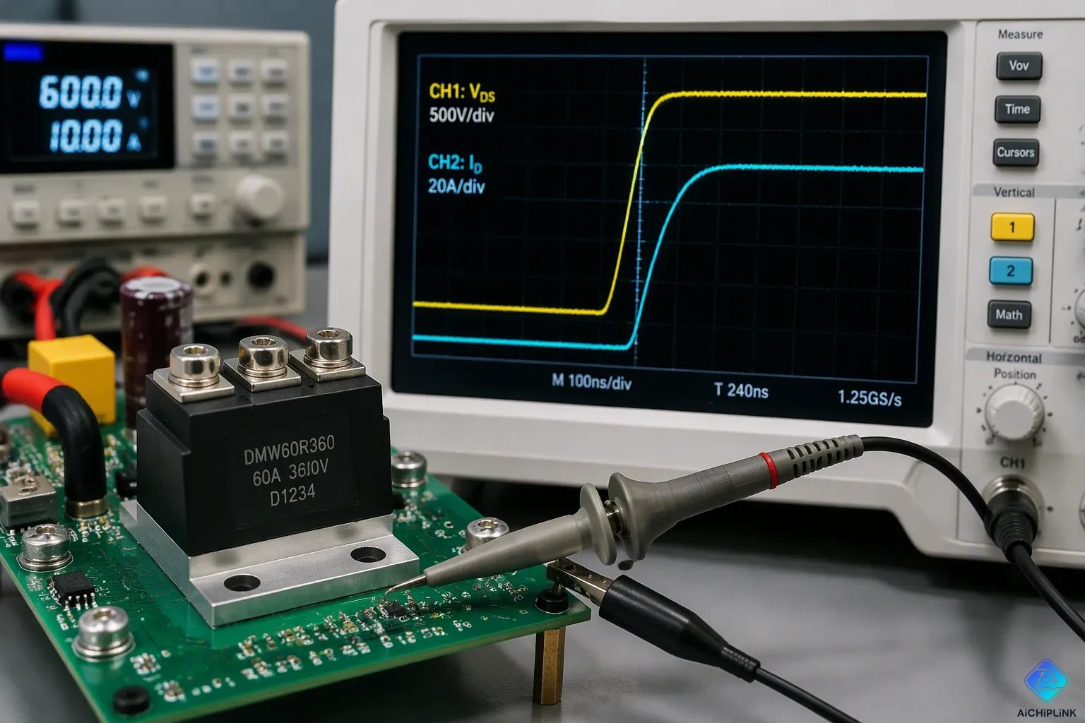
Typical dv/dt values for power devices range from hundreds of V/μs to tens of thousands of V/μs. Di/dt usually falls between tens and hundreds of A/μs. These dv/dt numbers depend on your device technology, gate drive strength, and circuit parasitics. Voltage slew rate changes with device type too.
You should care because too much dv/dt can cause a device to turn on when you don't want it to. High di/dt causes heat to build up in one spot and can lead to failure. Both voltage and current slew rates put reliability at risk. Managing current spikes is a must.
This section explains real dv/dt and di/dt ratings, the dangers they pose, and ways to keep your solid-state relays within safe limits.
Key Takeaways
-
dv/dt measures how quickly the voltage changes across a switch. A high dv/dt can turn on a device by accident.
-
di/dt tells how fast current changes. High di/dt makes hot spots that damage the device.
-
Datasheets show the maximum dv/dt and di/dt ratings. Going beyond these limits causes failures or unwanted behavior.
-
Inductive loads increase dv/dt stress when the device turns off. Capacitive loads increase di/dt stress when the device turns on.
-
You can use snubbers or gate resistors to make switching slower. This keeps voltage and current within safe limits.
What dv/dt and di/dt Mean
You see dv/dt and di/dt in every power switching circuit. These two rates tell you how fast voltage and current change when switching. Knowing them helps you predict stress and EMI.
Defining Voltage Slew Rate
The rate of change of voltage (dv/dt) shows how fast the voltage across a switch goes up or down. You write it in volts per microsecond (V/μs). For example, a dv/dt of 500 V/μs means it rises 500 V each microsecond. Silicon IGBTs usually give dv/dt values of several thousand V/μs. GaN and SiC devices reach dv/dt values over 100 V/ns (100,000 V/μs). High dv/dt can create a lot of electromagnetic interference (EMI). This fast change can also cause capacitive coupling problems. You must think about this EMI when you design filters. You measure this rate with a high‑speed probe and an oscilloscope. Standards like IEC 60034‑25 set limits on peak slew rates for motor drives. Manufacturers list these limits in their datasheets so you can stay safe. Understanding the rate of change of voltage helps you design filters.
Defining Current Slew Rate
The rate of change of current (di/dt) tells you how fast the current changes. You measure it in amperes per microsecond (A/μs). A di/dt of 50 A/μs means the current goes up by 50 A each microsecond. Silicon IGBTs have di/dt values around tens of A/μs. GaN HEMTs reach di/dt values of 1 A/ns (1,000 A/μs). Such high di/dt values put stress on the device and can cause hot spots. Such fast changes also increase core losses in magnetics. For solid‑state relays, managing this rate is key to prevent failure. You must check the ratings in the datasheet to avoid damage. You measure this rate using a Rogowski coil, which directly senses the derivative. Pulse Electronics has made precision winding techniques for accurate measurement. The STPMxx ICs from STMicroelectronics meet Class 0.2 accuracy when used with such sensors. You must think about the rate of change of current when picking magnetics. Understanding both rates helps you pick the right parts for your design. Always think about both rates when building your power stage.
dv/dt Ratings and Risks
Every power switch can only handle a certain speed of voltage change. You must follow this limit. The dv/dt rating is the fastest voltage change that won't turn on the device by itself. This number matters most for thyristors, triacs, and other latching parts. It also matters for solid‑state relays that use these parts.
Datasheet dv/dt Limits
The dv/dt rating is in every datasheet for thyristors and triacs. You will see it listed as "critical rate of rise of off‑state voltage" or a similar name. This value tells you the fastest voltage change allowed across the anode‑to‑cathode path. The part stays off below this limit, even with no gate drive. Above this limit, the part may turn on by itself.
A typical thyristor might have a dv/dt rating of 100 V/μs. A high‑speed version could reach 1,000 V/μs or more. The maximum dv/dt depends on junction temperature and anode voltage. Higher temperatures lower the maximum dv/dt. Higher anode voltage also lowers it. You must check the test conditions in the datasheet. The rating often applies at a certain temperature and voltage.
The maximum rate of rise also changes with gate impedance. A low‑impedance gate path raises the maximum dv/dt. A high‑impedance gate path lowers it. You control this with a gate resistor or a gate‑cathode capacitor. The datasheet will show these test conditions clearly.
Consequences of Exceeding dv/dt
When voltage rises too fast, a displacement current flows through the device's capacitance. This current can act like a gate signal. The part turns on when you did not want it to. This is called unintended triggering or false turn‑on.
A false turn‑on in a bridge circuit can short both switches at the same time. The current spike that follows can destroy the part in microseconds.
The maximum allowable rate of rise also affects avalanche breakdown. A fast voltage transient can push the junction into avalanche. The electric field becomes too strong. Current flows in a narrow path. Local heating rises fast. The part may fail.
High dv/dt also couples noise into nearby circuits. This noise can trigger other parts in your system. You must manage dv/dt and di/dt together for reliable operation. The dv/dt rating is not just a suggestion. It is a hard limit that decides whether your circuit works or fails.
di/dt Ratings and Risks
The di/dt rating tells you the fastest current change a device can handle without malfunction or damage. This limit matters for all switches, but it is very important for diodes and thyristors. You must follow this number to keep your circuit working.
Datasheet di/dt Limits
You can find the di/dt rating in the datasheet under "critical rate of rise of on-state current" or a similar name. This value shows the highest di/dt the part can survive. A typical thyristor might have a rating from 50 A/μs to 200 A/μs. The exact number depends on junction temperature, gate drive strength, and how long the current pulse lasts. Higher temperatures lower the maximum di/dt. A weak gate signal also lowers it. You must check the test conditions carefully. The datasheet often gives the rating at a specific case temperature and gate current. Some parts allow higher di/dt values with a strong gate pulse. Others need a slow start to stay within limits. For solid-state relays, the di/dt rating often appears with the dv/dt and di/dt limits. You should compare these ratings against your worst-case switching conditions. A part that works at 100 A/μs in the lab might fail at 80 A/μs in your circuit if stray parts add stress.
Consequences of Exceeding di/dt
When current rises too fast, the heat does not spread evenly. It gathers in a small area near the gate or edge. This local overheating can melt the silicon and break the part. The risk grows with high di/dt because the current crowds into narrow channels. Reverse recovery in diodes is a common failure mode. Here is what happens:
-
During reverse recovery, stored charge in the diode junction must be removed before the diode can block reverse voltage.
-
This stored charge creates a temporary reverse current. If the current changes suddenly, the transition becomes very fast.
-
The sudden current change causes voltage overshoots and spikes because of circuit stray inductance and the fast stop of current.
-
These voltage spikes stress the circuit and can damage the diode or other parts, especially in fast switching circuits.
-
Hard recovery, where reverse current drops suddenly, is very dangerous because it creates high voltage spikes and stress. Soft recovery reduces spikes by making the current go down slowly.
You can lower these risks with a few practical steps:
-
Improve circuit layout to reduce stray inductances, which can make voltage spikes worse during switching.
-
Add snubbers or damping circuits where needed to stop voltage overshoot and reduce EMI caused by reverse recovery.
A diode that fails during reverse recovery often shorts. The resulting current surge can destroy other parts. You must manage di/dt and dv/dt together for reliable operation. The di/dt rating is not a soft limit. It decides if your device survives the next switching cycle.
Load Effects and Safe Limits
How Load Types Shape Slew Rates
The load you hook up directly changes how much dv/dt and di/dt stress your switch takes. A resistive load keeps voltage and current lined up, so the stress is not as bad. An inductive load makes a fast rise when you turn off the switch. This high dv/dt can make thyristors and triacs trigger when you don't want them to. Capacitive loads pull a big inrush current at turn-on, which pushes the di/dt higher.
| Load Type | dv/dt Stress Characteristic |
|---|---|
| Resistive | Less extreme; voltage and current in phase. |
| Inductive | High dv/dt when switched off; can cause rapid rise and unexpected triggering. |
Parasitic parts in your layout make these effects worse. Parasitic inductance fights fast current changes, following V = L(di/dt). A high di/dt through the power loop inductance makes a voltage overshoot across the switch. This overshoot can go past the device breakdown rating. The stored energy then rings with parasitic capacitance, causing ringing and EMI. Common source inductance fights the gate drive, slowing switching and lowering slew rates but raising losses.
Snubbers, Gate Resistors, and Datasheet Selection
You have a few ways to stay inside safe limits. An RC snubber across the switch soaks up ringing energy but burns extra power. Pick the resistor and capacitor values to damp the resonance without too much loss. A gate resistor is easier. Raising gate resistance slows the switching speed, lowering both switching slew rates. The trade-off is higher switching losses. Soft-switching methods like zero-voltage switching get rid of fast transitions completely but need resonant circuits.
Component selection is your first line of defense. For solid-state relays, check the dv/dt and di/dt ratings in the datasheet. Look for "critical rate of rise of off-state voltage" for dv/dt and "critical rate of rise of on-state current" for di/dt. Always check the test conditions. Higher junction temperatures lower both limits. A stronger gate drive boosts the current slew rate handling. Compare these values against your worst-case conditions. If your layout has high parasitic inductance, pick a switch with higher limits or add a snubber to protect the switch.
dv/dt and di/dt are real limits that decide if your device works or breaks. These values are very different for silicon, silicon carbide, and gallium nitride technologies. Your circuit design, like layout and gate drive, also changes these dv/dt and di/dt levels. Always check the ratings in the datasheet. Test worst-case conditions before you build hardware. Use snubbers or gate control to stay safe when you need more protection. As switching gets faster, handling voltage and current becomes more important for reliability and EMI rules. High voltage and fast current changes hurt reliability and make noise. Future designs will need even tighter control of these parameters. Solid-state relays need careful attention to these limits. You must take these parameters seriously in every design.

Written by Jack Elliott from AIChipLink.
AIChipLink, one of the fastest-growing global independent electronic components distributors in the world, offers millions of products from thousands of manufacturers, and many of our in-stock parts is available to ship same day.
We mainly source and distribute integrated circuit (IC) products of brands such as Broadcom, Microchip, Texas Instruments, Infineon, NXP, Analog Devices, Qualcomm, Intel, etc., which are widely used in communication & network, telecom, industrial control, new energy and automotive electronics.
Empowered by AI, Linked to the Future. Get started on AIChipLink and submit your RFQ online today!
Frequently Asked Questions
What happens if I exceed the dv/dt rating?
The device can turn on without a gate signal. This unintended triggering can cause a short circuit. It often destroys the switch and other parts in your system.
How does a high di/dt cause damage?
A high di/dt creates localized hot spots inside the silicon. The current crowds into a small area. Melting occurs quickly. Diodes facing fast reverse recovery are especially at risk.
Are dv/dt and di/dt values the same for every switch?
No, they vary widely by technology. Silicon IGBTs handle slower changes. GaN and SiC switches switch much faster. You must check the specific ratings in each datasheet.
What can I do to lower the dv/dt stress?
You can raise the gate resistor value. This action slows down the voltage transition. You can also add an RC snubber across the switch. It absorbs the ringing energy.
Does my load type affect the stress on solid-state relays?
Yes, it does. Inductive loads create high voltage stress during turn-off. Capacitive loads cause high current surges during turn-on. You must select a relay rated for your load type.