Every time you plug in your phone charger or laptop, a silent conversion is happening. The grid delivers Alternating Current (AC), which swings back and forth 50 or 60 times a second. But your microchips need Direct Current (DC)—a steady, one-way flow of electrons.
The hero of this conversion is the Full Wave Rectifier.
Unlike the simpler "Half-Wave" rectifier, which throws away half the energy, the Full Wave Rectifier flips the negative side of the AC wave up, using the entire signal. This results in higher efficiency and smoother power.
This guide will break down the two main types—Center-Tapped and Bridge—and the math you need to design them.
1. The Basics: Why Half-Wave Isn't Enough
To understand "Full Wave," we must look at what it replaced. A Half-Wave rectifier uses a single diode to block the negative half of the AC sine wave.
- The Result: You get gaps in power delivery.
- Efficiency: Max $\eta = 40.6%$. Ideally, more than half your power is wasted.
- Ripple: Massive. It is very hard to smooth out.
The Full Wave Solution: A Full Wave rectifier steers the negative half-cycle so that it flows through the load in the same direction as the positive half.
- Efficiency: Max $\eta = 81.2%$.
- Result: A continuous stream of energy "humps" (Pulsating DC) with no gaps.
2. Type 1: The Center-Tapped Rectifier
This was the standard in the vacuum tube era. It uses a specialized transformer with a connection right in the middle of the secondary winding (the "Center Tap").
How It Works
It uses two diodes ($D_1$ and $D_2$).
- Positive Half-Cycle: The top of the transformer is positive. $D_1$ conducts. Current flows through the load.
- Negative Half-Cycle: The bottom of the transformer becomes positive relative to the center tap. $D_2$ conducts. Current flows through the load in the same direction.
The Disadvantage: It requires a Center-Tapped Transformer, which is physically larger and more expensive than a standard transformer. Also, each diode must block twice the voltage ($2V_m$), requiring higher-rated components.
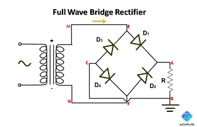
3. Type 2: The Bridge Rectifier (Industry Standard)
Today, 99% of power supplies use the Bridge Rectifier. It achieves full-wave rectification without a special transformer.
The Mechanism
It uses four diodes arranged in a diamond bridge topology ($D_1, D_2, D_3, D_4$).
- Positive Half-Cycle: Current flows through $D_1$ and $D_2$.
- Negative Half-Cycle: Current flows through $D_3$ and $D_4$.
In both cases, current enters the top of the load resistor and exits the bottom. The AC has been "rectified."
Why It Wins:
- Transformer: Works with any standard 2-wire transformer.
- Size: The 4 diodes are often packaged into a single, small chip (e.g., KBP206 or GBU808).
4. Critical Specs: PIV, Ripple, and Efficiency
When designing a power supply, you need to calculate three numbers.
1. Efficiency ($\eta$)
The ratio of DC output power to AC input power. $$\eta_{max} = \frac{8}{\pi^2} \approx 81.2%$$
2. Ripple Factor ($\gamma$)
The AC component remaining in the DC output (the "noise"). $$\gamma = \sqrt{(\frac{V_{rms}}{V_{dc}})^2 - 1} \approx 0.48$$
- Note: A lower number is better. Half-wave rectifiers have a terrible ripple of 1.21.
3. Peak Inverse Voltage (PIV)
This is the maximum voltage the diode must withstand when it is turned off (Reverse Biased). If you exceed this, the diode explodes.
- Bridge Rectifier: $PIV = V_m$ (Peak Voltage).
- Center-Tapped: $PIV = 2V_m$.
- Implication: For high-voltage applications, Bridge is much safer and cheaper because diodes don't need extreme voltage ratings.
5. Smoothing the Bumps: The Capacitor Filter
The output of a rectifier is not a straight line; it is Pulsating DC (0Hz to 100/120Hz). To make it usable for electronics, we add a Smoothing Capacitor in parallel with the load.
- Charging: The capacitor charges up to the peak voltage ($V_m$).
- Discharging: When the rectifier voltage drops, the capacitor releases its stored energy into the load, preventing the voltage from dropping to zero.
This transforms the "humps" into a nearly flat line with a slight wiggle (Ripple Voltage).
6. Comparison Summary
| Feature | Center-Tapped | Bridge Rectifier |
|---|---|---|
| No. of Diodes | 2 | 4 |
| Transformer | Center-Tapped (Bulky) | Standard (Compact) |
| PIV Rating | $2V_m$ (High Stress) | $V_m$ (Low Stress) |
| Ripple Factor | 0.48 | 0.48 |
| Output Frequency | $2 \times f_{in}$ | $2 \times f_{in}$ |
| Cost | High (due to Transformer) | Low |
7. Conclusion
Understanding Full Wave Rectifiers is the first step in mastering power electronics. While the Center-Tapped design has its place in history, the Bridge Rectifier is the modern champion due to its cost-efficiency and lower component stress. Whether you are building a linear power supply or analyzing a switch-mode input stage, the principles of commutating diodes remains the same.
Sourcing Rectifier Components Building a power supply? Visit Aichiplink.com to search for Bridge Rectifiers (like the GBU, KBPC series) and Smoothing Capacitors.

Written by Jack Elliott from AIChipLink.
AIChipLink, one of the fastest-growing global independent electronic components distributors in the world, offers millions of products from thousands of manufacturers, and many of our in-stock parts is available to ship same day.
We mainly source and distribute integrated circuit (IC) products of brands such as Broadcom, Microchip, Texas Instruments, Infineon, NXP, Analog Devices, Qualcomm, Intel, etc., which are widely used in communication & network, telecom, industrial control, new energy and automotive electronics.
Empowered by AI, Linked to the Future. Get started on AIChipLink.com and submit your RFQ online today!
Frequently Asked Questions
What is a full wave rectifier?
A full wave rectifier converts both halves of an AC waveform into DC, providing higher efficiency and smoother output than a half-wave rectifier.
What is the difference between bridge and center-tapped rectifiers?
A bridge rectifier uses four diodes and a standard transformer, while a center-tapped rectifier uses two diodes but requires a special center-tapped transformer.
Why is a bridge rectifier more commonly used?
Because it has lower PIV requirements, uses a smaller transformer, and is cheaper and more compact overall.
What is the ripple factor of a full wave rectifier?
The ripple factor is approximately 0.48, which is much lower than that of a half-wave rectifier.
Can a full wave rectifier produce pure DC?
No. It produces pulsating DC, which must be smoothed using capacitors or filters to obtain near-pure DC.
.png&w=256&q=75)


