Optical Encoders Explained: Types, Applications, and Selection Tips
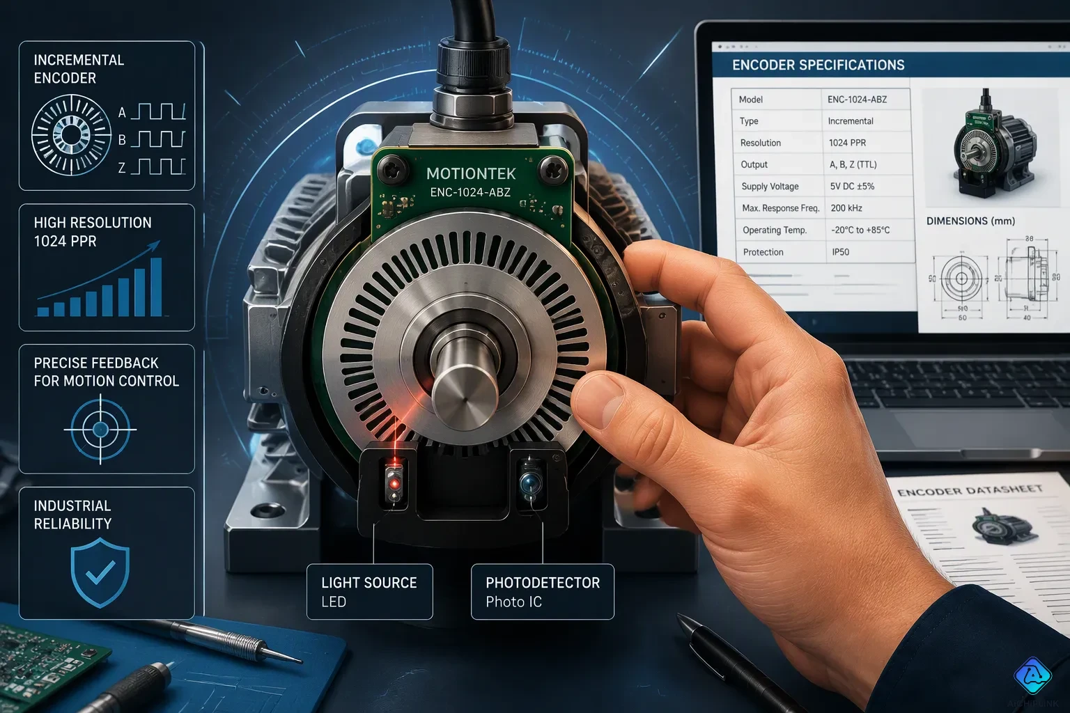
A robotic arm swings toward a weld seam. The joint must stop within a hair of the target angle. One wrong pulse, and the part fails inspection. An optical encoder solves this problem. This device turns mechanical motion into electrical signals by passing light through a patterned code disc onto a photodetector.
Engineers trust optical encoders for high resolution, accuracy, and reliability. These traits matter in precision motion control systems and in any machine that needs precise feedback. Designers often ask about the types, functions, and importance of these devices. They also want to know where optical encoders provide precise feedback for industrial automation. This article answers those questions and explains how to choose the right unit.
Key Takeaways
-
Optical encoders use light and a code disc to turn motion into electrical signals.
-
Pick rotary encoders when you need to measure shaft rotation. Choose linear encoders when you need to measure straight-line motion.
-
Absolute encoders keep track of their position even after the power goes out; incremental encoders need to be reset to a starting point.
-
Pick the right encoder for the place it will be used: optical for clean areas, magnetic for dirty ones.
-
Pick the lowest resolution that still does what you need. This saves money and cuts down on mistakes.
Optical Encoder Basics and Components
How Optical Encoders Work
An optical encoder measures position, speed, and direction by turning mechanical movement into electrical signals. The light path is simple. An LED sends a beam toward a detector. A code disc with slot-like openings sits between them and spins with the shaft. As the disc turns, its openings take turns letting light through and blocking it. Each opening that lines up sends a light pulse to the paired photodetector.
The photodetector, usually a set of photodiodes, turns those light pulses into electrical signals. Two signals sit 90 electrical degrees out of phase. An electronic circuit then squares the waveforms into digital high and low states. The processor reads one signal for rotation pulses and one for direction. This is the heart of how encoders work: light becomes pulses, and pulses become position, velocity, and direction data for the controller.
Key Components Explained
Four parts do the job. The table below shows each role.
| Component | Role |
|---|---|
| LED light source | Sends a beam toward the detector |
| Code disc | Alternating opaque and transparent segments block the beam as it spins |
| Photodetectors (A and B) | Turn light pulses into electrical signals 90 degrees out of phase |
| Output signal processor | Boosts and squares the quadrature outputs into digital pulses and a direction signal |
Structural layout splits into two families. Transmissive encoders put the source and detector on opposite sides of the disc, and light passes through the coded pattern. Reflective encoders mount the source, grating, and detector on the same side, and light bounces off reflective segments back to the sensors. Transmissive designs tend to give higher resolution and accuracy for precise feedback. Reflective designs suit systems with tight space and make alignment easier.
Optical encoders also lead on resolution. Magnetic encoders are tough but give lower resolution and accuracy than optical units. Capacitive types offer a wide resolution range at lower cost. Optical encoders remain the standard for high-resolution position and velocity feedback in precision motion control systems.
Types of Encoders: Rotary and Linear
Engineers group encoder types by the motion they measure and by how they report position. Both questions shape the final choice. Each answer quickly narrows the field.
Rotary vs. Linear Optical Encoders
The main types of optical encoders split by motion. Optical rotary encoders track shaft rotation. A clear disk carries evenly spaced opaque sections. An LED shines through the disk, and a photodetector senses the light. This makes a train of evenly spaced pulses, and the output is measured in pulses per revolution. Rotary units mount right on the shaft they monitor. Common designs carry 100 to 6000 segments per revolution, which gives 3.6° to 0.06° resolution. A linear optical encoder pairs a scanning unit with a glass scale mounted to a support. The scanning unit holds the light source, photocells, and scanning reticle. It turns motion along a guide rail into digital or analog signals.
| Aspect | Rotary Optical Encoder | Linear Optical Encoder |
|---|---|---|
| Motion measured | Rotary motion from a rotating shaft | Linear motion from a block on a guide rail |
| Construction | Coded disk, LED, photodetector; output in pulses per revolution | Scanning unit plus glass scale; tracks position change over time |
| Environment | Clean areas free of dust, oil, and debris | Dust- and debris-free areas; magnetic linear versions offer IP67 protection |
An optical encoder is very sensitive to dust. A dirty disk scatters light and corrupts the signal. Rotary encoders and linear scales both suffer here. Harsh plants therefore favor rugged magnetic or capacitive units. Glass scales also shatter under impact, so mounting care matters.
Incremental vs. Absolute Encoders
The difference between incremental and absolute encoders comes down to position memory. Incremental encoders count pulses. They report a change in position, not a specific location. Absolute encoders output a digital word proportional to angle. They need no reference position at power-up.
With incremental encoders, positional information is not kept after a power cycle and does not show a specific position, only a positional change. Meanwhile, an absolute encoder will tell you the exact position on power-up and shows a positional change and a specific position.
This incremental vs. absolute encoders split drives real design choices. Incremental optical encoders cost less upfront and use simpler electronics. They need a homing sequence at every startup. Homing also adds setup time in multi-axis systems. Absolute encoders cost more. They keep position through power loss and resist electrical noise. Absolute optical encoders report position over interfaces such as SSI, Profibus, or Ethernet. A 16-bit absolute unit resolves 65,536 positions per revolution. Angle encoders push measurement performance below one arc second. Incremental and absolute encoders both serve motion control well, yet they suit different budgets and reliability targets.
Linear encoders also come in several technology families: optical, magnetic, capacitive, inductive, and laser. Optical wins when accuracy and resolution matter most. Linear scales measure accuracy and resolution in tens of nanometers. Magnetic and inductive versions tolerate dirt and wider gaps but give lower accuracy. Laser versions offer nanometer-level accuracy at higher cost. Cost rises with precision across every family. These types of encoders share one rule: match the technology to the environment first. A designer picking a rotary or linear encoder should weigh resolution, accuracy, and working conditions together.
Optical Encoder Technology: Signals and Precision
Code Disc Design and Output Signals
The code disc sets the top limit on encoder performance. Its pattern of light and dark areas passes in front of the sensor, and the sensor turns that pattern into an electrical signal. The number of slots on the disc and the precision of the motion sensor together set the accuracy and resolution. Offset signals give precise motion information such as speed, and designers can combine multiple signal outputs for a more stable result.
Two disc designs shape the output. A masked encoder uses a fixed mask with perforated windows that lines up with the disc tracks. The open and closed window pattern at each rotational arc identifies position, and each sensor produces a single signal. A phased-array encoder averages multiple signal outputs into one. That averaging produces more stable and reliable signals and handles vibration and shock with less installation precision than a masked design.
Output format also controls precision. Incremental encoders send two square waves, A and B, in quadrature, plus an index pulse Z once per revolution. TTL output uses differential wiring to cancel noise over long cables. HTL suits discrete counting, while SinCos analog waves allow external interpolation. A 2048 PPR HTL unit gives 11-bit resolution; the same 2048 cycles per revolution with 4096x interpolation reaches 23-bit resolution. For absolute encoders, Gray code changes only one bit per step and reduces communication errors, while binary code can flip several bits at once and invite errors at high speed.
Error Compensation Methods
Errors creep in from several directions. Manufacturing tolerances, bearing eccentricity, and assembly variation create periodic errors. Temperature swings, vibration, and electromagnetic interference add drift. Shaft misalignment and signal processing limits add to these as well. Optical encoder technology counters these with layered fixes.
| Error Source | Compensation Method |
|---|---|
| Manufacturing inaccuracies | Parametric approximation of systematic error, real-time correction |
| Thermal expansion | Low-CTE materials, matched CTE, thermal error models |
| Vibration and shock | Real-time output signal correction |
| High-frequency sub-divisional error | Look-up tables, digital filtering |
Multiple readheads offer a mechanical route. Two diametrically opposed readheads cancel eccentricity and odd harmonics, and four also fight bearing wander. Error maps store a correction table after calibration; a 100-point map addresses roughly the first 14 harmonics. A taper mount turns an eccentric ring into slight swash, so 1 µm of eccentricity on a 200 mm ring becomes 0.002° of swash. Together these methods protect position, speed, and direction data and deliver precise feedback in demanding motion systems.
Integration and Selection Tips
Interfaces and Environmental Factors
The interface you pick affects data safety and safe motion. SSI gives a simple, one-way link with optional parity and clock rates from 100 kHz to 2 MHz, but no real-time feedback. BiSS-C adds two-way register access, CRC error checking, daisy-chaining, and clock speeds up to 10 MHz. Renishaw notes that SSI has no data integrity checking, while BiSS-C guards position data with a CRC and prevents uncontrolled axis motion. Cable length also counts: BiSS-C reaches 100 m, SSI about 50 m. For Ethernet setups, EtherCAT gives steady synchronization, and PROFINET supports diagnostics and device setup. TTL works for short runs, and HTL handles longer, noisier routes.
| Feature | BiSS-C | SSI |
|---|---|---|
| Direction | Bidirectional | Unidirectional |
| Data integrity | CRC | Optional parity |
| Max clock | 10 MHz | 2 MHz |
| Real-time | Yes | No |
The environment decides whether an optical encoder lasts. Indoor units usually run from -10°C to +70°C; outdoor units go from -40°C to +85°C and need thermal compensation. Indoor vibration stays below 2000 Hz and 100 m/s²; outdoor exposure reaches 5000 Hz and beyond 300 m/s². Dust blocks the optical path, so sealed housings rated IP65 or IP67 protect the disc. EMI calls for conductive enclosures, twisted-pair cabling, differential signaling, and proper grounding. Outdoor deployments cost 40–60% more to make, plus 15–25% for compensation. Designers who pick the right encoder weigh these stressors before price.
Best Practices for Selection
A good process starts with the motion profile. Velocity control favors incremental units; precise positioning favors absolute encoders. Next, check the environment, then confirm mechanical limits such as hollow-bore mounting. Match the protocol to the drive, and count total cost of ownership, including homing time.
-
Check that the model meets every system specification.
-
Align the mount within ±0.05 mm.
-
Validate all electrical connections.
-
Install the required safety barriers.
-
Confirm the output works with the controller.
-
Run initial tests and fix faults early.
Resolution and accuracy are not the same. Accuracy means the gap between target and actual position; resolution means distinguishable steps. Most applications need only about 0.1°, or 8–10 arcminutes, while high-precision work demands better than ±10 arc-seconds. Choose the lowest resolution that meets the task. Extra counts raise cost, processing time, and jitter, and high-velocity axes have less time to read each cycle. Signal conditioning must hold bandwidth above 1 MHz, noise immunity better than -60 dB, and phase matching within ±2.5° electrical. Interpolation reaches 4096x but works best near 1024x with a signal-to-noise ratio above 40 dB. Keep 10 mm clearance from nearby components, and use shielded twisted pairs beyond 6 ft. These habits help any team choose the right encoder for closed loop motion feedback.
Rotary and linear encoders measure different kinds of motion. Incremental units count pulses and need a reference point. Absolute units report their position as soon as they power on. What the application needs drives the final choice.
A simple framework helps. First, define the accuracy you need on the load side. Set the resolution fine enough for the control loop, since resolution finer than true accuracy does not make the axis more accurate. Then weigh the environment and interface together. Dust, vibration, and temperature may point to a sealed or non-optical design. The interface must match the controller, and a clean protocol cannot fix a weak measurement signal.
Designers can apply these tips with confidence. Careful selection turns a demanding motion challenge into reliable, precise feedback.

Written by Jack Elliott from AIChipLink.
AIChipLink, one of the fastest-growing global independent electronic components distributors in the world, offers millions of products from thousands of manufacturers, and many of our in-stock parts is available to ship same day.
We mainly source and distribute integrated circuit (IC) products of brands such as Broadcom, Microchip, Texas Instruments, Infineon, NXP, Analog Devices, Qualcomm, Intel, etc., which are widely used in communication & network, telecom, industrial control, new energy and automotive electronics.
Empowered by AI, Linked to the Future. Get started on AIChipLink and submit your RFQ online today!
Frequently Asked Questions
When should a designer choose optical over magnetic?
Optical encoders give higher resolution and accuracy than magnetic units. Magnetic types put up with dust, oil, and wider gaps. A clean axis that needs precision favors optical. A dirty plant floor with rough feedback needs favors magnetic. Match the technology to the environment first, then compare resolution.
Does higher resolution always mean better accuracy?
No. Accuracy measures the gap between target and actual position. Resolution measures steps you can tell apart. An axis with fine steps but poor accuracy still misses the target. Most tasks need only about 0.1°, or 8–10 arcminutes. High-precision work demands better than ±10 arc-seconds.
Why pick an absolute encoder over an incremental one?
An absolute unit reports its exact position at power-up. It needs no homing sequence and resists electrical noise. An incremental unit counts pulses and loses position after a power cycle. Multi-axis systems save setup time with absolute feedback. Tight budgets often favor incremental designs.
What environmental limits should a buyer check first?
Dust, temperature, vibration, and EMI decide survival. Sealed housings rated IP65 or IP67 protect the disc from debris. Indoor units usually run from -10°C to +70°C; outdoor units span -40°C to +85°C. Conductive enclosures and twisted-pair cabling fight interference.
Which interface suits a long cable run?
BiSS-C reaches 100 m with CRC error checking and two-way register access. SSI covers about 50 m with optional parity and no real-time feedback. EtherCAT and PROFINET serve Ethernet setups. TTL works for short runs, and HTL handles longer, noisier routes.