Building an Ultrasonic Radar using Arduino and Processing
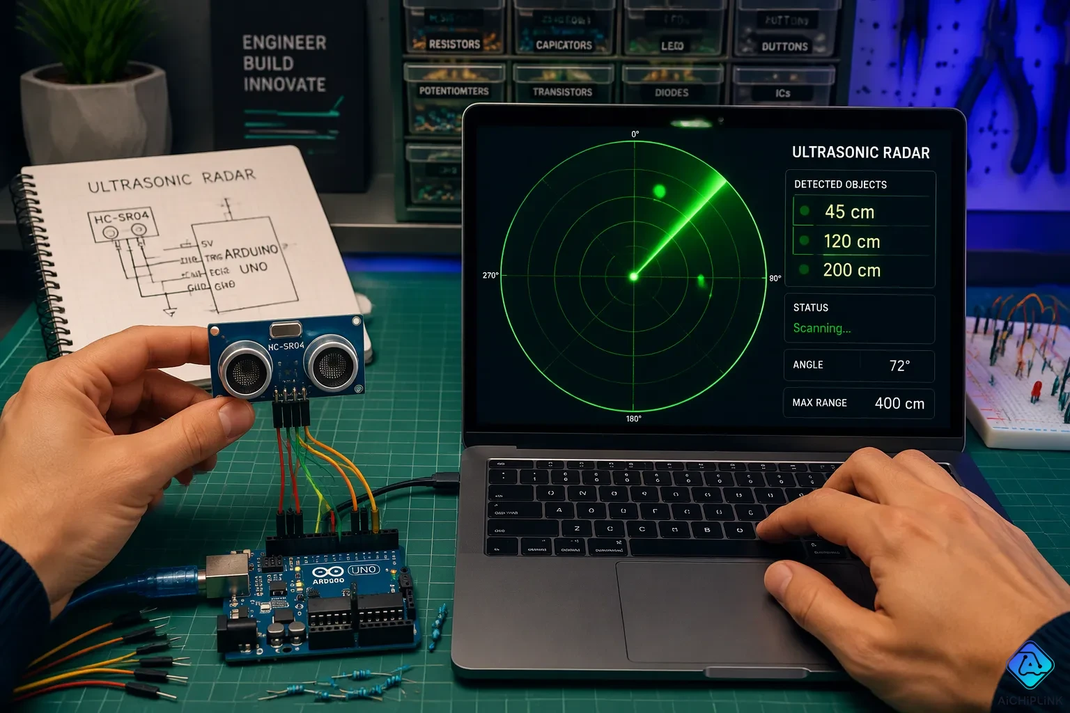
An ultrasonic radar is a distance-sensing project. You mount an HC-SR04 sensor on a servo, and the servo sweeps the sensor side to side. Arduino measures the distance to nearby objects and streams that data over serial. Processing reads the stream and draws a live radar screen.
Three building blocks carry the whole project. The sensor gathers distance data. The Arduino sketch controls the sweep and sends readings. The Processing sketch turns those readings into a moving display.
Your finished build detects objects from roughly 2 cm to 400 cm away. It then maps each one on screen as the sweep passes. You get a working radar you can watch in real time.
Key Takeaways
-
An ultrasonic radar uses a sensor on a servo to sweep an area and measure distances.
-
Arduino controls the servo and sensor, then sends angle and distance data to Processing.
-
Processing reads the data and draws a live radar screen with a sweep line and object blips.
-
Match the baud rate and port name in both Arduino and Processing to avoid a blank display.
-
Filter out readings outside 2 cm to 400 cm to remove false blips and keep the display clean.
Ultrasonic Radar Components
Parts List
You need five parts to build the hardware side of this ultrasonic radar. Each part has a clear job in the build.
| Part | Role in the Build |
|---|---|
| HC-SR04 sensor | Sends out ultrasonic pulses and measures the echo return time |
| SG90 servo | Rotates the sensor across a sweep arc |
| Arduino board | Runs the sketch, reads distance, and drives the servo |
| Jumper wires | Carry signals and power between the parts |
| Breadboard | Holds the connections without soldering |
The HC-SR04 fits best as the distance sensor. It works well for this project because it reports range in a simple pulse format. The SG90 servo is a small, lightweight motor. It suits the sensor mount because the HC-SR04 weighs very little. An Arduino Uno or similar board handles both the sensor timing and the servo signal without strain. Jumper wires and a breadboard keep the circuit easy to change while you test.
Software Setup
Two programs run this project. The Arduino IDE uploads the sketch that controls the servo and reads the sensor. The Processing IDE runs the display sketch on your computer. Install both before you wire anything.
The two programs talk over a serial connection. Arduino sends angle and distance values. Processing reads them and draws the radar screen. Set the same baud rate in both sketches. A mismatch here is the most common reason the display stays blank.
You can swap parts with code changes. A different ultrasonic sensor may need a new trigger and echo routine. A different display, such as an LCD, needs a new output sketch. The core logic stays the same.
Wiring the Sensor and Servo
Mounting the Sensor
Start with the mechanical side. Press the HC-SR04 onto the servo horn. The sensor has two round transducers on its face. Point them outward, away from the servo body. A small piece of double-sided foam tape or a dab of hot glue holds the sensor in place. Keep the glue away from the transducer faces.
Next, secure the servo itself. Tape or clamp the servo body to a stable base, such as a small box or a breadboard edge. The servo must not wobble during the sweep. A loose mount makes the distance readings jump around. Check that the sensor can rotate freely through its full arc without hitting the base or any wires.
Pin Connections
The HC-SR04 has four pins. Wire them to the Arduino with standard 5V operation.
| HC-SR04 Pin | Arduino Connection |
|---|---|
| VCC | 5V |
| GND | GND |
| Trig | Digital pin 9 |
| Echo | Digital pin 10 |
The servo has three wires. Connect the brown or black wire to GND and the red wire to 5V. Route the signal wire, usually orange or yellow, to a PWM-capable pin such as digital pin 11. The servo draws current in short bursts during movement. A weak USB supply can cause the servo to twitch. If that happens, power the servo from a separate 5V source and tie its ground to the Arduino ground.
Double-check every connection before you apply power. A swapped VCC and GND on the sensor can damage it. Keep the jumper wires short and tidy. Long, loose wires pick up noise and make the readings less stable.
Arduino Sketch

The Arduino sketch does two jobs at once. It fires the sensor and times the echo. It also steps the servo through its arc. Both tasks share one loop, so the timing between them matters. A rushed loop gives you jittery readings and a jerky sweep.
Distance and Sweep Logic
Start each reading with a short trigger pulse. Pull the trigger pin low for a moment, then high for about ten microseconds, then low again. The sensor responds by sending a burst of sound. The echo pin goes high for the time the sound takes to travel out and back. The pulseIn function measures that high time in microseconds. Give pulseIn a timeout value. Without one, a missing echo can stall the loop and freeze the sweep.
Convert the time to distance with a simple relation. Sound travels at roughly 343 meters per second in air at room temperature. Distance in centimeters equals the echo time in microseconds multiplied by 0.0343, then divided by two. The division by two matters. The sound covers the distance to the object and back, so the one-way range is half the round trip. Readings outside the sensor's working range are not trustworthy. Treat anything under about 2 cm or over about 400 cm as no object.
Set the pin modes in setup. The trigger pin is an output and the echo pin is an input. Attach the servo before the first write. Then start the serial port and let the loop take over.
The sweep logic moves the servo in small steps. Attach the servo to pin 11 with the Servo library. Then write an angle, wait for the horn to settle, take a reading, and move to the next angle. A short delay after each step keeps the readings clean. Without it, the sensor fires while the mount still vibrates. Step through the arc one degree at a time, then reverse direction at each end. A direction variable flips the step sign and gives you a continuous back-and-forth sweep.
Serial Data Output
The display needs two numbers per reading: the angle and the distance. Format them as a single line with a separator between them. A comma works well. End every line with a newline character so Processing knows where one reading stops and the next begins.
Open the serial port in setup with Serial.begin. Pick one baud rate and use the same value in the Processing sketch. Print the angle first, then the comma, then the distance. Use Serial.print for the values and Serial.println for the final number so the line ends cleanly. Send the line once per servo step. This steady stream gives the display a fresh point for every position in the sweep.
A sample line might read 90,45. That means the sensor pointed at 90 degrees and found an object 45 cm away. Processing splits the line at the comma and turns each half into a number.
Keep the output simple. Extra text or debug messages break the parser on the other end. If you need to test, comment out the print statements rather than adding labels. A clean stream of angle-and-distance pairs keeps your ultrasonic radar display running smoothly.
Processing Radar Display
The Processing sketch turns raw serial text into a moving picture. It opens the serial port, reads each line, and splits the line into two numbers. Then it draws a radar screen with a sweeping line and marks each detected object as a blip. This section shows you how each step works.
Parsing Serial Data
First, open the serial port in setup. Use the Serial class and pass the port name and baud rate. The baud rate must match the Arduino sketch exactly. A mismatch here leaves you with garbage characters or no data at all. On Windows, the port name looks like COM3. On macOS or Linux, it looks like /dev/ttyUSB0 or similar. You can find the correct port in the Arduino IDE under Tools > Port. You can also call Serial.list() to print every available port.
Next, read incoming data in draw. The Serial object gives you a readStringUntil method. Pass a newline character to it. This method returns one complete line, such as 90,45. Now split the line at the comma. The split function returns an array of two strings. Convert each string to a number with int. The first number is the angle. The second number is the distance. Store both values in variables for the drawing step.
Handle missing or malformed lines with care. A line might arrive empty or contain extra characters. Check the array length before you convert. Skip any line that does not split into exactly two parts. This guard keeps your sketch from crashing on a bad read. You can also print the raw line to the console during testing. Remove that print later for a cleaner run.
Visualizing the Ultrasonic Radar
Now draw the screen. Set the window size in setup to a square, such as 600 by 600 pixels. In draw, clear the background with a dark color. Draw a half-circle arc from 0 to 180 degrees. This arc represents the sweep range. Add range rings at fixed distances, for example every 100 cm. Label each ring with its distance value.
Place the radar center at the bottom middle of the window. Set centerX to width divided by 2 and centerY to height. Map the distance to a pixel radius with the map function. For a 400 cm maximum range, map 0 to 0 and 400 to width divided by 2. This scaling keeps every blip inside the arc.
The sweep line shows the current sensor angle. Convert the angle from degrees to radians. Processing's trigonometric functions use radians. Compute the end point of the line with cosine and sine. Draw a line from the center to that point. A bright color makes the sweep easy to see.
Plot each detected object as a blip. Use the angle and distance from the parsed data. Convert the angle to radians. Compute the x and y position with cosine and sine, scaled by the distance. Draw a small filled circle at that point. A red or yellow color stands out against the dark background. Clear old blips on each frame, or let them fade slowly to show a trail. This live drawing completes your Ultrasonic Radar display.
Testing and Troubleshooting
Sensor Calibration
Calibration starts with the range limits. Your HC-SR04 reports usable readings from about 2 cm to 400 cm. Treat anything outside that window as noise. A reading of 0 cm or a sudden jump to a huge value usually means the echo never returned. Filter those values out before you send them to the display. This simple check removes most false blips from your Ultrasonic Radar screen.
Noisy readings need smoothing. The sensor can report slightly different distances for a still object. Take several readings at each angle and average them. A short median filter also works well. Collect three or five samples, sort them, and keep the middle value. This step rejects the odd spike without slowing the sweep much. Test with a flat target, such as a book, at a known distance. Compare the reported value to a tape measure. Adjust your filter until the numbers stay steady.
Common Fixes
Most problems trace back to a few repeatable causes. Work through this list before you change any code.
| Symptom | Likely Cause | Fix |
|---|---|---|
| No data in Processing | Wrong COM port | Check Tools > Port in the Arduino IDE and match the port name in your sketch |
| Garbled characters | Baud rate mismatch | Set the same baud rate in both sketches |
| Servo twitches or resets | Weak power supply | Power the servo from a separate 5V source with a shared ground |
| Erratic distance values | Loose or long wires | Shorten the jumpers and reseat every connection |
Start with the wiring. A single loose jumper causes more faults than any software bug. Confirm the trigger and echo pins match your sketch. Then check the serial link. The port name and baud rate must agree on both sides. Print the raw serial line to the console during testing. If you see clean angle-and-distance pairs there, the problem sits in the drawing code, not the connection.
You now have a working Ultrasonic Radar. The servo sweeps the HC-SR04 across its arc. Arduino measures each echo and streams angle-and-distance pairs over serial. Processing reads that stream and draws the sweep line and object blips in real time.
Several upgrades are worth trying next. Widen the servo sweep for broader coverage. Add a median filter to steady the distance readings. Trigger a buzzer when an object crosses a set threshold. Log each reading to a file for later review.
Tweak the code freely. Change the colors, the range rings, or the sweep speed. Share your version with others who are building the same project.

Written by Jack Elliott from AIChipLink.
AIChipLink, one of the fastest-growing global independent electronic components distributors in the world, offers millions of products from thousands of manufacturers, and many of our in-stock parts is available to ship same day.
We mainly source and distribute integrated circuit (IC) products of brands such as Broadcom, Microchip, Texas Instruments, Infineon, NXP, Analog Devices, Qualcomm, Intel, etc., which are widely used in communication & network, telecom, industrial control, new energy and automotive electronics.
Empowered by AI, Linked to the Future. Get started on AIChipLink and submit your RFQ online today!
Frequently Asked Questions
How far can this Ultrasonic Radar detect objects?
The HC-SR04 reports usable readings from about 2 cm to 400 cm. Treat anything outside that window as noise. A reading near zero or a sudden huge jump usually means the echo never came back. Filter those values out before they reach the display.
Why does my Processing window stay blank?
Check two things first. The port name in your sketch must match the port shown under Tools > Port in the Arduino IDE. The baud rate must also match on both sides. A mismatch in either setting leaves you with no data or garbled characters.
Can I use a different servo or sensor?
Yes. The core logic stays the same. A different ultrasonic sensor may need a new trigger and echo routine. A different servo may need a new signal pin. Adjust the code to match your parts, then test the sweep before you trust the display.
Does the sensor work in the dark?
Yes. The HC-SR04 sends sound waves, not light. It detects objects the same way at night as in daylight. Soft materials like cloth absorb more sound, so they may return a weaker echo or none at all.
How do I make the distance readings steadier?
Take several readings at each angle and average them. A short median filter also works well. Collect three or five samples, sort them, and keep the middle value. This rejects odd spikes without slowing the sweep much.