DIY 48V Current Monitor Using ESP32
Imagine your solar battery bank losing power sooner than you thought. You need live data on the current to figure out the problem. Working with 48V can seem scary. But with clear steps and safety rules, you can do this safely.
The ESP32 is a great choice for this project. It has built-in Wi-Fi and Bluetooth so you can check your system from your phone or computer. You get live data without having to stand near high-voltage equipment.
Your goal is to build a safe, accurate ammeter that you can access without wires. This project creates a reliable ESP32 ammeter for 48V systems. You will learn helpful information about your power use and battery health.
Key Takeaways
-
Always put safety first when working with 48V systems. Use insulated tools and fuses, and follow electrical codes to stop arcs and fires.
-
Pick the current sensor that fits your project. Shunt resistors give very precise readings, while Hall-effect sensors keep circuits separate but can drift from zero over time.
-
Calibrate your ESP32's ADC and sensor to make sure your current readings are accurate. Use a multimeter and software filters to make the readings more reliable.
-
Use MQTT and IoT dashboards to watch your battery's health live. This helps you choose wisely and make the battery last longer.
-
Begin with a basic setup, then slowly add extras like alerts and cloud storage to make your monitoring system better.
Building an ESP32 Ammeter for 48V Systems
Monitoring current in a 48V system helps keep your battery working longer. If you don't have live data, you can't tell your State of Charge (SoC) or Depth of Discharge (DoD). These numbers affect how long your battery lasts. For example, keeping SoC between 20% and 80% puts less stress on the battery cells. Discharging only to 50% DoD gives you many more charge cycles than deep discharges. A current monitor gives you the data to make good choices.
Real-time tracking also makes things work better. MPPT controllers recalculate working points hundreds of times each second. They use live current data to change voltage and current ratios as needed. This process gets the most energy from solar panels when sunlight changes. Your esp32 ammeter for 48v system gives you the same information for your whole setup.
Safety First: Understanding 48V Risks
You need to be careful with 48V. Many people think low voltage can't arc or cause fires. That is not true.
"Only high-voltage systems arc." → False. Low-voltage arcs can happen when there is a fault. Also, "Low voltage can't start a fire." → False, because current, not voltage, causes overheating and fire risk.
A 48V battery bank can release hundreds of amps in an instant. If you drop a metal tool across the terminals, it creates a strong arc. The arc can last for seconds while you try to react. Having several battery banks in parallel makes the danger greater because the short-circuit current goes up a lot.
Protect yourself with easy habits. Wrap your tools in electrical tape. Wear safety goggles and insulating gloves. Use proper footwear. Install fuses to find faults and stop short circuits. Follow your local electrical rules. Under IEC 62368-1, 48V DC is below the 60V level that is thought safe for regular people. But you still shouldn't leave exposed connectors out. Fire danger is still real.
Core Concepts of DC Current Measurement
Measuring DC current is different from measuring AC. AC systems change direction many times each second. DC flows in one direction only. This difference matters when you choose a sensor.
For DC, you have two main ways. Shunt resistors measure current by detecting voltage drop across a known resistance. Hall-effect sensors detect the magnetic field around a wire. Each method has trade-offs in accuracy, cost, and isolation.
You also need to understand battery health signs. State of Health (SoH) compares current capacity to original design capacity. A drop to 70-80% usually means the battery’s useful life is ending. Round-trip efficiency measures energy output versus input. High efficiency above 95% for LiFePO4 batteries wastes less solar energy. A clear drop shows aging or system problems.
These ideas prepare you for picking a sensor. The next section helps you choose the right component for your current range and accuracy needs.
Choosing the Right Sensor
Your sensor choice determines how accurate and safe your whole monitoring system will be. You need to pick a sensor that fits your current range and how precise you want your readings. A 0-20A system needs different parts than a 0-50A setup. Think about your battery bank's highest discharge rate before you buy anything.
Hall-Effect vs. Shunt Resistors
Two main technologies are used to measure DC current. Each one has its own pros and cons in cost, accuracy, and how hard it is to install.
| Factor | Hall Effect Sensor | Shunt Resistor |
|---|---|---|
| Cost | Higher cost; may reduce need for extra isolation parts | Lower cost; simple passive part |
| Temperature Stability | Can drift with heat; needs compensation | More stable; may need heat control |
| Suitability | Best for high-voltage, isolated, or car uses | Best for low-cost, precise DC readings where isolation is not key |
| Measurement Type | Measures both AC and DC; no contact | Mostly DC; needs contact |
Hall-effect sensors detect the magnetic field around a wire. They give galvanic isolation naturally because they never touch the circuit directly. This makes them good for high-voltage systems. But they have accuracy issues. Outside magnetic fields, temperature changes, and sensor placement all change their readings. One engineer on a DIY forum said it plainly: "Zero drift will be your #1 problem to solve with anything hall based." Another added, "ACSxxx sensors aren't actually very good - you'll probably get within your few% though."
Shunt resistors work differently. They measure current by checking the voltage drop across a known resistance. This method gives high accuracy for DC readings. Outside magnetic fields do not mess with the results. Temperature stability is much better than Hall-effect options. The downside is power loss. The voltage drop creates heat that you must handle. Higher currents need bigger shunts with proper heat control.
| Aspect | Hall Effect Sensor | Shunt Resistor |
|---|---|---|
| Accuracy | Lower due to outside fields, heat, and placement effects | High accuracy; less affected by outside factors |
| Isolation | Galvanic isolation built-in; no direct contact | Needs direct contact; no built-in isolation |
| Power Loss | Very little power loss (no contact) | Voltage drop causes power loss; heat control needed |
| Installation | Easier to install; offset drift and calibration may be needed | More complex install; works with standard control systems |
For your esp32 ammeter for 48v project, think about what matters most. If you need steady zero readings and exact numbers, go with a shunt. One forum expert said, "I would definitely look at using shunt resistors rather than hall sensors if you want a reliable ZERO."
Integrated Modules: PZEM-004T and INA219
You do not have to build a sensor from scratch. Several ready-made modules make your build much easier.
The PZEM-004T is a full solution. This module measures voltage, current, and power at the same time. It talks over a simple serial interface. You get all the data you need from one small board. The module handles high currents without extra signal parts. This cuts down wiring and possible mistakes. For a 48V battery bank, this module is a good place to start.
The INA219 offers different benefits. This chip uses an I2C interface, which connects easily to the ESP32. It gives high accuracy for lower current uses. The module has a built-in amplifier and ADC. You can read current and voltage with great detail. But you must pick the right shunt resistor for your expected current range. This module works best for systems using up to a few amps.
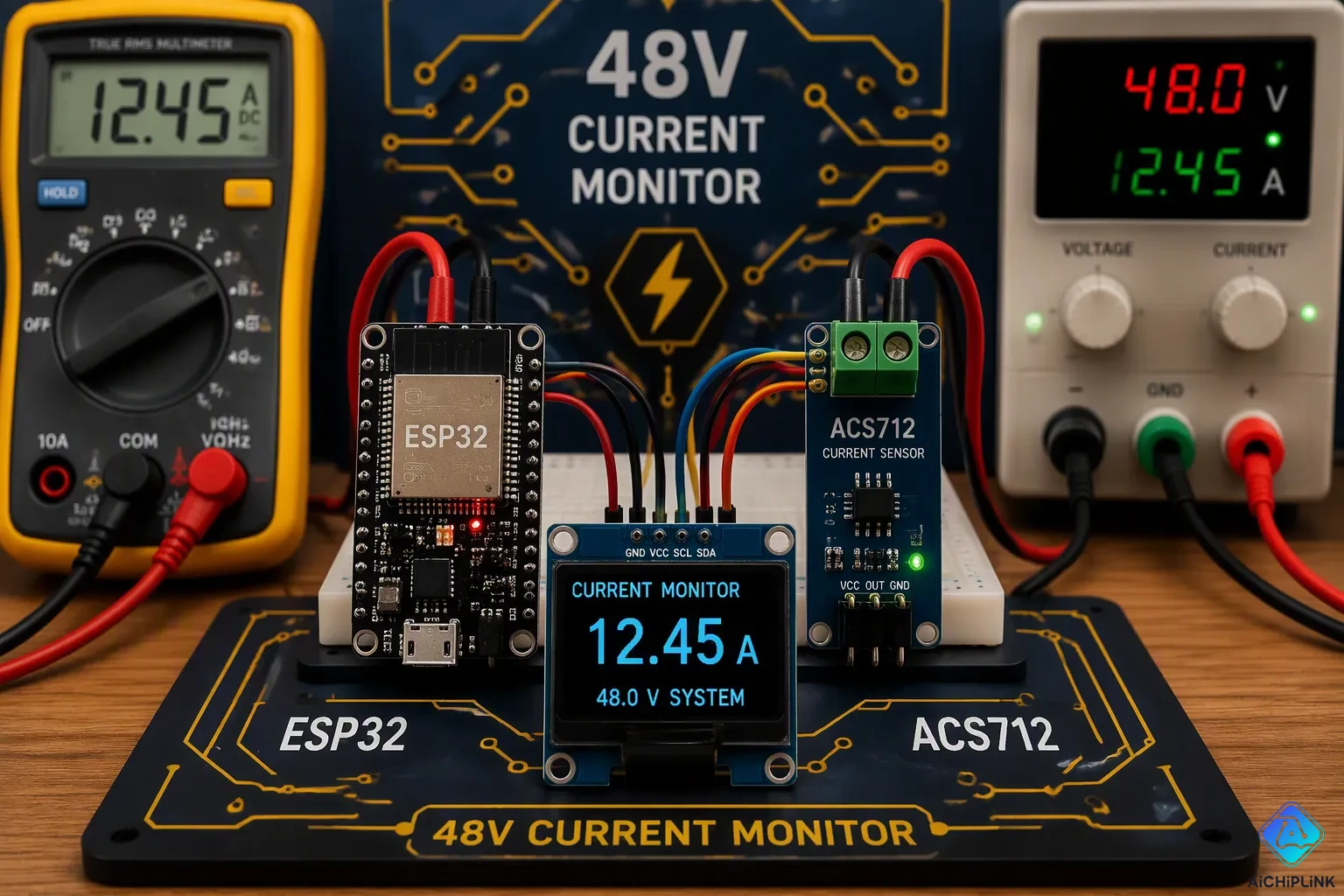
Many hobbyists pick the ACS712 as a common choice. This Hall-effect module shows up in many guides. Its low cost and easy availability make it popular. But its accuracy limits make it less good for reliable monitoring. The zero-drift problem mentioned earlier hits this sensor hard. You might get readings within a few percent, but you cannot trust the starting point.
Your final pick depends on what you need. A PZEM-004T gives you a full monitoring setup with little work. An INA219 gives precision for smaller currents. A shunt-based design gives the best accuracy for tough jobs. No matter which one you choose, you build a strong base for your esp32 ammeter for 48v system.
Wiring and Isolation for Safety
Now you move from theory to physical connections. This stage demands your full attention. A wiring mistake at 48V can damage your equipment or cause injury. You need a clear plan before you touch any wire.
Voltage Dividers for ESP32 ADC
The ESP32 reads analog signals through its ADC pins. These pins accept only 0 to 3.3V. Your 48V battery bus far exceeds that limit. You cannot connect the battery directly to the ESP32. You need a voltage divider to step down the voltage safely.
A voltage divider uses two resistors in series. The battery voltage drops across both resistors. You tap the middle point between them. That middle point connects to your ESP32 ADC pin. The formula for the output voltage is Vout = Vin × R2 / (R1 + R2). Here, R1 connects to the positive battery terminal, and R2 connects to ground.
Choose resistor values carefully. High resistance values minimize current draw from your battery. A divider with 100kΩ and 10kΩ resistors draws less than 0.5mA from a 48V source. That tiny drain will not affect your battery's state of charge. However, high resistance also means slower response times. The ADC input capacitance must charge through these resistors. For most monitoring applications, this delay matters little.
You also need a protection diode across the ADC pin. This diode clamps any voltage spike above 3.3V or below ground. A simple 3.3V Zener diode works well. Add a small capacitor, around 100nF, from the ADC pin to ground. This capacitor filters noise from switching loads.
Connecting the Sensor and Powering the ESP32
Your current sensor needs careful thought about isolation. The sensor sits in the path of your battery current. You must prevent any path for high voltage to reach your ESP32.
If you use a shunt resistor, check your ground connections. The shunt's low side must not share a ground with the ESP32's power supply. A common ground creates a ground loop. This loop introduces noise and can create an unsafe path. Use an isolated DC-DC converter for the ESP32 if you choose a shunt.
Hall-effect sensors offer built-in isolation. The sensor detects magnetic fields without electrical contact. You still need to verify the isolation rating. Check the datasheet for the voltage rating between the sensing element and the output pins. A sensor rated for 100V isolation works safely in your 48V system.
Applicable standard threshold: Per UL 60950-1 and related safety guidelines, PCB isolation requirements (creepage and clearance) become mandatory when the operating voltage exceeds 30V AC or 60V DC. Since a DIY 48V current monitoring project operates below the 60V DC hazardous threshold, it falls outside the mandatory isolation spacing rules of UL 60950-1. However, designers should still reference this standard for best practices if the project interfaces with higher-voltage circuits or is classified as IT equipment.
Your ESP32 needs a clean power source. Do not power it from the same supply as your sensor. Use a dedicated buck converter that steps down from 48V to 5V. This converter feeds the ESP32's USB or 5V pin.
| Specification | Key Detail |
|---|---|
| Input Voltage Range | 36–75V to cover all common battery chemistries (e.g., LiFePO₄ discharged ~40V, fully charged ~58.4V) |
| Thermal Derating | Check datasheet's output current vs. ambient temperature curve; a rated 15A module may deliver only 9A at 50°C |
| Protections | Must include overvoltage (OVP), overcurrent (OCP), overtemperature (OTP), and reverse‑polarity input protection |
| Load Regulation | ≤±2% from no‑load to full‑load to prevent resets or USB disconnects |
| Physical Form Factor | Consider screw terminals vs. solder pads, heatsink compatibility, and IP rating (e.g., IP67 for truck‑mounting) |
A buck converter with these specifications keeps your ESP32 stable. It prevents voltage spikes from damaging your microcontroller. It also isolates the ESP32 from noise on the battery bus. This clean power source ensures accurate readings from your esp32 ammeter for 48v system.
Place a fuse between the battery positive terminal and your entire monitoring circuit. This fuse protects your wiring and your ESP32. Choose a fuse rated slightly above your expected maximum current. This fuse acts as your first line of defense against shorts.
Double-check every connection before applying power. Use a multimeter to verify continuity. Confirm that your voltage divider output stays below 3.3V. Test the buck converter output before connecting the ESP32. These checks take minutes and prevent costly mistakes.
Your wiring plan now protects both you and your equipment. The next step brings your hardware to life through code.
Programming the ESP32 for Accurate Readings
Your hardware is ready. Now you need code that turns raw signals into trustworthy numbers. Component tolerances mean your sensor output will not match the datasheet exactly. You must calibrate your specific setup to get accurate readings from your esp32 ammeter for 48v system.
Calibrating the Sensor and ADC
The ESP32 ADC has built-in calibration data stored in eFuse memory. Each chip records its own offset and gain values during manufacturing. The analogReadMilliVolts() function uses this factory data to return voltage directly in millivolts. This corrects chip-to-chip variations that would otherwise skew your readings.
The ESP32 stores per-chip calibration data in eFuse memory. For example, at 0dB attenuation, the factory calibration records an init code of 1364 at 0V and a cal code of 1958 when 400 mV is applied. This data is used by
analogReadMilliVolts()to correct for chip-to-chip variations, which is essential for accurate current sensing where even a few millivolts of offset can translate to significant current error.
Set your ADC attenuation to match your sensor output range. Use analogSetAttenuation(ADC_11db) to expand the measurable range to 0-3.3V. This setting ensures you capture the full signal from your current sensor without clipping.
| Technique | Implementation / Key Detail | Relevance to Current Monitoring |
|---|---|---|
| Calibration via analogReadMilliVolts() | Returns voltage in mV using factory eFuse data; corrects offset, gain, and reference errors. | Directly improves voltage-to-current conversion accuracy from sensors like ACS712 or shunt-based circuits. |
| Attenuation Setting | analogSetAttenuation(ADC_11db) expands range to 0–3.3V, matching typical sensor outputs. | Ensures the full current-sensor signal range is captured without clipping. |
| Moving Average Filter | Averages 16 samples (e.g., total += analogReadMilliVolts(34); then divide by 16). | Smooths out rapid fluctuations in current readings caused by electrical noise. |
| Exponential Moving Average (EMA) | filtered = alpha * reading + (1 - alpha) * filtered; with alpha ~0.2. | Provides real-time smoothing with low memory use, ideal for dynamic current monitoring loops. |
| Hardware Noise Reduction | Add 100 nF capacitor between ADC pin and GND; use short wires; stable power supply. | Reduces high-frequency interference that corrupts low-level current sensor signals. |
The ESP32 ADC also shows non-linearity. The relationship between input voltage and digital output is not perfectly straight. This deviation appears most strongly near the lower and upper ends of the measurement range. Simple gain or offset correction cannot remove these systematic errors. You can run a calibration program on your specific chip to generate a custom lookup table. This table maps each raw ADC value from 0 to 4095 to a corrected value. Remember that this correction applies only to your specific device.
Converting Raw Data to Current and Voltage
You need a reference source to calibrate your current readings. A precision digital multimeter works well for this task.
-
Connect your multimeter in series with the load to measure actual current.
-
Log the raw voltage reading from your sensor when no current flows to establish a baseline offset.
-
Apply a small current and record both your sensor reading and the multimeter reading.
-
Increase the current gradually through your full rated range, recording both values at each step.
-
Plot the measurements and fit a linear model: Voltage = Gain × Current + Offset.
-
Use the derived gain and offset values in your code to convert raw sensor voltage into actual current.
Apply software filters to stabilize your readings. A moving average filter that samples 16 times and divides by 16 works well for steady loads. An exponential moving average with alpha around 0.2 provides smoother real-time tracking for dynamic loads. Add a 100 nF capacitor between your ADC pin and ground to reduce high-frequency noise.
Your calibration data transforms raw ADC values into meaningful current measurements. Your esp32 ammeter for 48v system now reports accurate, reliable data you can trust for monitoring battery health and system performance.
Visualizing Data with IoT Dashboards
Your esp32 ammeter for 48v system now sends correct readings out. Raw numbers on a serial monitor do not help you choose. You need a dashboard that shows a clear picture of your battery's health. IoT dashboards fix this by showing real-time data you can use.
Setting Up MQTT for Data Streaming
MQTT is a simple messaging protocol for devices with low bandwidth. Your ESP32 sends current readings to a topic on the network. A broker gets these sent messages and gives them to subscribers. Any dashboard software linked to that broker gets updates right away.
First, pick an MQTT broker. HiveMQ Cloud has a free plan for testing. Make an account on their site. Click "HiveMQ Cloud" and then "Create New Cluster." Pick the serverless option. After the cluster is ready, go to access management. Make credentials that let you both publish and subscribe. Keep the password the system makes.
Your ESP32 links to the broker with a connection string. For normal links without encryption, use mqtt://your-broker-url:1883. For secure links, use mqtts:// on port 8883. WebSocket choices also work for dashboards in browsers.
Reliability is key when watching important battery systems. MQTT has three quality of service levels for sending data.
| QoS Level | Delivery Guarantee | Best Use Case |
|---|---|---|
| 0 | At most once, no acknowledgment | High-frequency, non-critical data where speed matters most |
| 1 | At least once with PUBACK confirmation | Smart metering or predictive maintenance where duplicates are tolerable |
| 2 | Exactly once via four-step handshake | Mission-critical over-current alerts in unstable networks |
QoS 0 works well for your usual current readings when things are stable. Use QoS 2 for alerts you cannot lose.
Building a Simple Web Dashboard
Your data now flows into the broker. You need a dashboard to see it. Many popular platforms link easily to an MQTT feed.
Home Assistant is great for home energy tracking. It joins your ESP32 topics. You make dashboard cards showing current, voltage, and power live. Another strong setup uses InfluxDB and Grafana. InfluxDB keeps your time-series data. Grafana makes visual dashboards with graphs and gauges you can change. An official Grafana Labs tutorial shows this same workflow with an ESP32 board. The microcontroller sends sensor data over Wi-Fi to InfluxDB. Grafana then shows the results on a live dashboard.
The dashboard gives real-time measurement of your 48V current. You see live data that helps you make better charging plans. This view raises uptime by spotting issues early. You save power by charging during off-peak times based on current patterns. The dashboard sends alerts right away when current or voltage passes your limits. This stops dangerous problems like over-discharge. You make your battery last longer with exact state tracking.
For an easier way, make a web server on the ESP32 itself. The microcontroller hosts a small HTML page. You use any browser on your home network to reach it. This method needs no outside services.
Save your data to an SD card or a cloud service for past analysis. You watch long-term patterns in battery health. You find performance issues before they cause breakdowns.
You have built a full monitoring system. You began with safety rules for 48V work. You picked the right sensor for your current range. You wired everything with proper isolation. You adjusted your readings and programmed the ESP32. At the end, you made a dashboard to view your data live.
This esp32 ammeter for 48v system gives you live insight into your battery's health. You can find issues early. You can improve charging cycles. You can stop over-discharge damage.
Now grow your project. Add over-current alerts. Send data to the cloud. Add temperature sensors. Each addition builds your skills.
You now have the know-how to take on advanced IoT energy monitoring projects with confidence.

Written by Jack Elliott from AIChipLink.
AIChipLink, one of the fastest-growing global independent electronic components distributors in the world, offers millions of products from thousands of manufacturers, and many of our in-stock parts is available to ship same day.
We mainly source and distribute integrated circuit (IC) products of brands such as Broadcom, Microchip, Texas Instruments, Infineon, NXP, Analog Devices, Qualcomm, Intel, etc., which are widely used in communication & network, telecom, industrial control, new energy and automotive electronics.
Empowered by AI, Linked to the Future. Get started on AIChipLink and submit your RFQ online today!
Frequently Asked Questions
Is 48V really dangerous to work with?
Yes, 48V can hurt you badly. The voltage alone won't give you a strong shock, but the current can cause dangerous arcs and fires. A short circuit can release hundreds of amps in an instant. Always use fuses and insulated tools. Turn off the power before you touch any connections.
Which sensor should I choose for my project?
Pick a sensor based on your current range and how precise you need it to be. The PZEM-004T measures voltage, current, and power all at once. This makes it the simplest choice. The INA219 gives very accurate readings for lower currents under a few amps. For the most steady zero readings, use a shunt-based design instead of a Hall-effect sensor.
Why does my Hall-effect sensor show current when nothing is connected?
This issue is called zero drift. Hall-effect sensors react to outside magnetic fields and temperature changes. Even tiny shifts move the starting reading. You can fix this by adjusting the offset in your code. Measure what the sensor shows with no current flowing. Then subtract that number from every future reading.
Can I connect the 48V battery directly to my ESP32?
No, never connect 48V straight to the ESP32. The ADC pins only accept 0 to 3.3V. You need a voltage divider with two resistors to lower the voltage safely. Add a Zener diode and a capacitor to guard the pin from spikes and noise.
Do I need a multimeter to calibrate my current sensor?
A multimeter makes calibration much simpler, but you can use other known loads instead. Connect a device with a known current draw, like a specific light bulb or resistor. Measure the sensor output and figure out the relationship. For the best accuracy, use a precision digital multimeter as your reference.