Table of Contents
- 1.0 How Does an Optocoupler Work? The Principle of Light-Based Isolation
- 2.0 A Breakdown of the Main Types of Optocouplers
- 3.0 Common Optocoupler Applications Across Electronics
- 4.0 How to Select and Test an Optocoupler: A Practical Guide
Have you ever designed a circuit where a sensitive, low-voltage microcontroller needs to control a high-voltage device? The biggest challenge is the danger of electrical noise or catastrophic voltage spikes jumping from the high-power side to your delicate logic circuits. This is where you need a bridge that isn't a bridge at all. This optocouplers guide is for you. Optocouplers, also known as opto-isolators or photocouplers, are the unsung heroes of electronic safety, creating a gap of complete electrical isolation between circuits. With the industrial automation market projected to grow significantly in 2025, the demand for reliable circuit isolation has never been higher. This article will walk you through exactly what optocouplers are, how they work, the different types available, and how to choose the perfect one for your project.
1.0 How Does an Optocoupler Work? The Principle of Light-Based Isolation
To truly appreciate an optocoupler, you need to think of it not as a single component, but as two separate circuits that communicate without touching. It’s like sending a message across a chasm with a flashlight instead of building a physical bridge. This "air gap," known as galvanic isolation, is the optocoupler's superpower.
1.1 What is an Optocoupler (Opto-Isolator)?
An optocoupler is an electronic component that transfers an electrical signal between two isolated circuits using light. It consists of two main parts sealed in a light-proof package (typically a DIP package):
- An Input Light Source: Almost always an infrared light-emitting diode (LED).
- An Output Photosensor: A light-sensitive device such as a phototransistor, photodiode, or photo-TRIAC.
When a current flows through the input LED, it emits light. This light travels across the internal gap and strikes the photosensor, which then allows current to flow in the completely separate output circuit. No electrons ever cross the gap, only photons.
[Insert image: A diagram showing the inside of an optocoupler, with an LED on the input side and a phototransistor on the output side, separated by a visible isolation barrier. Alt Text: Internal diagram of an optocoupler illustrating the LED, photosensor, and the principle of galvanic isolation.]
1.2 Understanding Current Transfer Ratio (CTR)
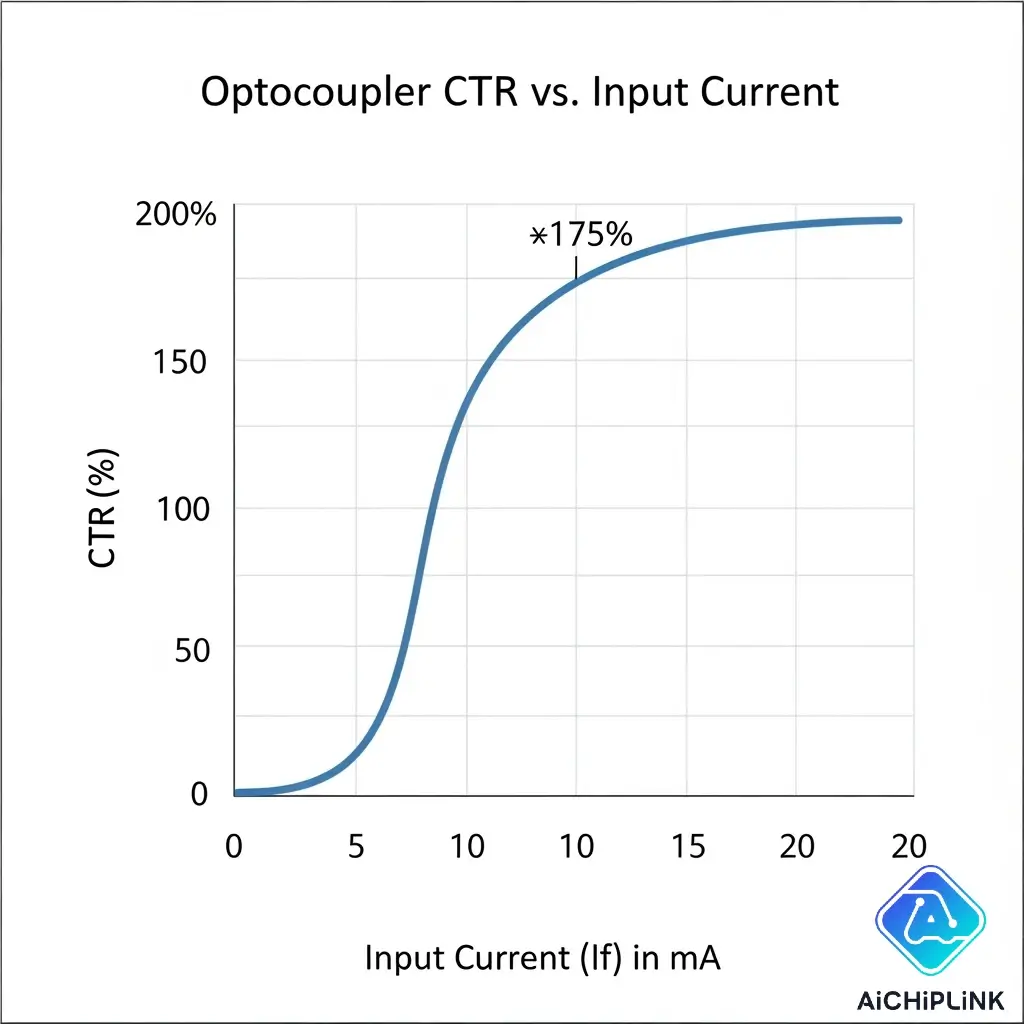
One of the most critical parameters of an optocoupler is its Current Transfer Ratio (CTR). It is the ratio of the output current (at the collector of the transistor, Ic) to the input current (flowing through the LED, If), usually expressed as a percentage.
CTR = (Ic / If) * 100%
A CTR of 50% means that for every 10mA of current you put into the LED, you will get 5mA of current at the output transistor. CTR is not a fixed value; it varies with input current, temperature, and component age, a crucial factor to consider during circuit design.
1.3 Key Parameter: Optocoupler Isolation Voltage
The isolation voltage is the entire reason optocouplers exist. This rating, given in kilovolts (kV), specifies the maximum voltage difference the component can withstand between its input and output circuits before the isolation barrier breaks down. For industrial or medical equipment, high isolation voltage is a non-negotiable safety requirement.
2.0 A Breakdown of the Main Types of Optocouplers
Optocouplers are categorized based on the type of photosensor used on the output side. This choice dictates the device's speed, output current capabilities, and suitability for AC or DC circuits.
"The type of output stage in an optocoupler defines its personality—whether it's a fast and precise digital switch or a robust controller for AC power."
2.1 Phototransistor Optocouplers
This is the most common and versatile type. The output stage is a bipolar NPN or PNP phototransistor. They offer a good balance of speed and a decent CTR, making them perfect for isolating general-purpose digital signals, such as in switch-mode power supplies.
2.2 Photodarlington Optocouplers
This type uses a Darlington pair of transistors for the output, which provides a much higher CTR (often over 1000%). The trade-off is that they are significantly slower than standard phototransistor types. They are used in applications requiring high current gain with a small input current, like driving solenoids or small relays directly.
2.3 Photo-TRIAC Optocouplers
Designed specifically for AC power control, these optocouplers have a TRIAC as the output stage. This allows a low-voltage DC signal from a microcontroller to safely control a high-voltage AC load like a motor, dimmer, or solid-state relay. They are the cornerstone of modern AC load management.
2.4 High-Speed Optocouplers
For isolating high-speed data buses like SPI or I²C, standard phototransistors are too slow. High-speed optocouplers use a photodiode and an integrated amplifier circuit as the output stage. This allows them to achieve data rates well into the megabits-per-second (Mbps) range, preserving signal integrity across the isolation barrier.
Here is a quick comparison:
| Optocoupler Type | Primary Use Case | Speed | CTR / Gain | Output Type |
|---|---|---|---|---|
| Phototransistor | General DC Signal Isolation | Moderate | Moderate | DC |
| Photodarlington | High-Gain DC Applications | Slow | Very High | DC |
| Photo-TRIAC | AC Load Control | Slow | N/A | AC |
| High-Speed | Data Bus Isolation | Very Fast | Low | DC |
3.0 Common Optocoupler Applications Across Electronics
Optocouplers are found in countless devices, providing silent, essential protection. Their ability to eliminate ground loops and block high-voltage transients makes them indispensable.
3.1 Power Supply Feedback Loops
In a switch-mode power supply (SMPS), an optocoupler provides a feedback path from the high-voltage secondary side back to the primary-side controller chip. This allows the controller to regulate the output voltage while remaining safely isolated from the dangerous output potentials.
3.2 Microcontroller I/O Isolation
When a microcontroller needs to read signals from or send signals to a noisy industrial environment, optocouplers are used on the I/O pins. They protect the delicate microcontroller from voltage spikes and ground noise that could otherwise cause crashes or permanent damage. A great example can be found in industrial PLC designs where circuit robustness is key.
3.3 AC Motor Control
A Photo-TRIAC optocoupler allows a simple digital output pin from an Arduino or other microcontroller to control the speed and power of an AC motor. This is the basis for simple fan speed controllers, light dimmers, and other home automation projects.
4.0 How to Select and Test an Optocoupler: A Practical Guide
Choosing the right component and verifying its function are key skills for any electronics designer. This section of our optocouplers guide provides practical, actionable advice.
4.1 Key Factors for Selecting the Right Optocoupler
When browsing a catalog of opto-isolators, consider these points:
- Isolation Voltage: Must be higher than the maximum potential difference your circuits will ever experience.
- Current Transfer Ratio (CTR): Choose a range that ensures the output transistor will be fully saturated (turned on) given your input current limitations.
- Bandwidth / Speed: Must be fast enough for your signal's data rate. Don't use a slow Darlington type for a high-speed signal.
- Output Type: Does your load require DC (transistor) or AC (TRIAC) switching?
- Package Type: Ensure the physical package (DIP, SOIC, etc.) fits your PCB layout.
4.2 Optocoupler vs. Solid-State Relay: What's the Difference?
While both use opto-isolation and can switch loads, they are designed for different jobs.
- An optocoupler is a signal-level component designed for isolating signals, providing feedback, and driving small loads.
- A Solid-State Relay (SSR) is a complete, packaged device designed to switch high-power AC or DC loads. It's essentially a heavy-duty power switch that contains an optocoupler (often a Photo-TRIAC type) and a power switching element inside.
4.3 How to Test an Optocoupler Step-by-Step
You can perform a simple go/no-go test on a phototransistor optocoupler with a multimeter and a power source.
- Identify Pins: Use the datasheet to find the LED's anode/cathode and the transistor's collector/emitter.
- Test the LED: Use your multimeter's diode check function on the input pins. It should behave like a normal LED.
- Test the Transistor: Set the multimeter to measure resistance across the collector and emitter. It should read as an open circuit (infinite resistance).
- Test the Switching: While measuring the collector-emitter resistance, apply power to the input LED through a current-limiting resistor (e.g., 5V with a 330Ω resistor). The resistance should drop to a very low value. If it does, the optocoupler works.
In conclusion, optocouplers are fundamental building blocks for safe and reliable electronic design. By creating a protective barrier of light, they allow disparate parts of a system—high-power and low-power, noisy and clean—to communicate effectively without interfering with or destroying one another. As technologies like electric vehicles, solar inverters, and smart industrial controls become more prevalent, the role of the humble optocoupler in ensuring system safety and integrity will only continue to grow.
Ready to build safer, more robust circuits? Browse our extensive catalog of high-performance optocouplers at aichiplink.com and find the perfect isolation solution for your next project!

Written by Jack Elliott from AIChipLink.
AIChipLink, one of the fastest-growing global independent electronic components distributors in the world, offers millions of products from thousands of manufacturers, and many of our in-stock parts is available to ship same day.
We mainly source and distribute integrated circuit (IC) products of brands such as Broadcom, Microchip, Texas Instruments, Infineon, NXP, Analog Devices, Qualcomm, Intel, etc., which are widely used in communication & network, telecom, industrial control, new energy and automotive electronics.
Empowered by AI, Linked to the Future. Get started on AIChipLink.com and submit your RFQ online today!
Frequently Asked Questions
What is the main purpose of an optocoupler?
The main purpose of an optocoupler is to provide galvanic isolation. It transmits an electrical signal between two isolated circuits using light, preventing high voltages or electrical noise from one circuit from affecting the other.
Does an optocoupler need a resistor?
Yes, the internal LED (light-emitting diode) of an optocoupler requires a series current-limiting resistor, just like any standard LED. Without it, the LED can be damaged by excessive current.
Are optocouplers bidirectional?
No, standard optocouplers are unidirectional. The signal can only pass from the input LED to the output photosensor.
How long do optocouplers last?
The primary aging factor in an optocoupler is the gradual degradation of the LED's light output over thousands of hours of use. This causes the CTR to decrease over time. Reputable manufacturers like Vishay provide detailed reports on this aging process, which must be accounted for in long-life designs.
Can an optocoupler be used for analog signals?
Yes, but it requires careful design. Because the CTR is non-linear, optocouplers are not inherently great for transmitting analog signals directly. However, they are commonly used in isolated analog feedback systems by operating them in a narrow, more linear region or by using specialized analog optocouplers with feedback photodiodes.


.png&w=256&q=75)


