The MAX232 IC has 16 pins. Each pin does a special job to help change voltage between TTL/CMOS and RS-232 signals. You need to know the max232 pinout to build circuits and fix problems. If you connect the pins wrong, the voltage may not be steady or data may not send right.
| Pin Number | Primary Function Description |
|---|---|
| 1 (C1+) | Connects to the positive side of an outside capacitor. This helps the charge pump make RS-232 voltages. |
| 2 (Vs+) | Connects to the positive side of charge pump capacitors. This keeps voltage levels steady. |
| 3 (C1-) | Connects to the negative side of a capacitor. This helps flip voltage for doubling. |
| 4 (C2+) | Connects to the positive side of another capacitor. This helps make RS-232 voltage. |
| 5 (C2-) | Connects to the negative side of a capacitor. This helps keep voltage steady. |
| 6 (Vs-) | Gives a steady -5V for negative RS-232 signal voltages. |
| 7 (T2OUT) | Sends out TTL changed to RS-232 signal (Tx output). |
| 8 (R2IN) | Takes in RS-232 input signals to change to TTL. |
| 9 (R2OUT) | Sends out RS-232 changed back to TTL signal. |
| 10 (T2IN) | Takes in TTL input signals to change to RS-232. |
| 11 (T1IN) | Takes in TTL input signals to change to RS-232 (second channel). |
| 12 (R1OUT) | Sends out TTL signals after RS-232 is changed (second channel). |
| 13 (R1IN) | Takes in RS-232 signals to change to TTL (second channel). |
| 14 (T1OUT) | Sends out TTL changed to RS-232 signal (second channel). |
| 15 (GND) | Ground pin that keeps the IC working steady. |
| 16 (VCC) | +5V power pin that gives power to the inside parts. |
Every pin is important for making steady voltage and moving data well. If you follow the pin setup, you can stop mistakes and make sure devices talk to each other without problems.
Key Takeaways
-
The MAX232 has 16 pins. Each pin has a special job. These pins help change voltage levels. This lets TTL/CMOS and RS-232 devices talk to each other.
-
You must connect power, ground, capacitors, and data pins the right way. This helps keep voltage steady. It also stops mistakes in sending data.
-
The chip uses a charge pump. It needs extra capacitors outside the chip. These make higher positive and negative voltages. This is needed for RS-232 signals. It all works from just one 5V power source.
-
Always find pin 1 by looking for the notch or dot on the chip. This helps you not make wiring mistakes. Check the capacitor values and where you put them very carefully.
-
If you follow the right pinout and connection rules, you avoid problems. This stops data mistakes, no communication, or damage to the MAX232.
MAX232 Pinout
Pin Numbering
When you look at a MAX232 chip, you will see a small notch or a dot on one end of the IC. This mark helps you find pin 1. Hold the chip so the notch or dot is at the top. Pin 1 sits at the top left corner. The pins go around the chip in a counterclockwise direction. You count from pin 1 down the left side, then across the bottom, and up the right side to pin 16 at the top right. This standard pin numbering makes it easy to follow the max232 pinout in any project.
Tip: Always check the notch or dot before you place the MAX232 on a breadboard or PCB. This step helps you avoid mistakes with the pin configuration.
Pin Configuration Table
The max232 pinout uses 16 pins. Each pin has a special job. Some pins connect to capacitors, some handle power, and others move data between TTL and rs232 levels. The table below shows the pin names with functions for each pin. You can use this table to check your connections and make sure your circuit works well.
| Pin Number | Pin Name | Function |
|---|---|---|
| 1 | C1+ | Connects to the positive side of the first external capacitor. |
| 2 | VS+ | Positive voltage output from the charge pump. Connect a capacitor here. |
| 3 | C1- | Connects to the negative side of the first external capacitor. |
| 4 | C2+ | Connects to the positive side of the second external capacitor. |
| 5 | C2- | Connects to the negative side of the second external capacitor. |
| 6 | VS- | Negative voltage output from the charge pump. Connect a capacitor here. |
| 7 | T2OUT | RS-232 level output for transmitter 2. |
| 8 | R2IN | RS-232 level input for receiver 2. |
| 9 | R2OUT | TTL/CMOS level output from receiver 2. |
| 10 | T2IN | TTL/CMOS level input for transmitter 2. |
| 11 | T1IN | TTL/CMOS level input for transmitter 1. |
| 12 | R1OUT | TTL/CMOS level output from receiver 1. |
| 13 | R1IN | RS-232 level input for receiver 1. |
| 14 | T1OUT | RS-232 level output for transmitter 1. |
| 15 | GND | Ground. Connect to 0V. |
| 16 | VCC | Power supply. Connect to +5V. |
You can see that the max232 pinout includes both transmitter and receiver pins. These pins help you send and receive data between your microcontroller and rs232 devices. The capacitor pins support the charge pump inside the max232. This charge pump creates the higher and lower voltages needed for rs-232 signals. The power and ground pins keep the chip running.
When you follow the correct pin configuration, you make sure the max232 works as it should. Always double-check the pin names with functions before you connect anything. This habit helps you avoid damage and keeps your rs232 communication stable.
Working of MAX232 IC
Voltage Level Conversion
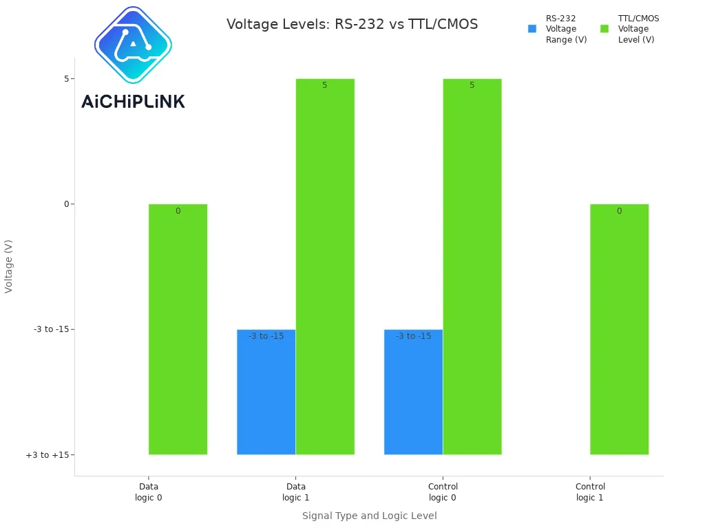
You use the MAX232 IC to connect devices that speak different voltage languages. Microcontrollers and logic circuits use TTL or CMOS levels, which means a logic "0" is 0 volts and a logic "1" is 5 volts. On the other hand, RS-232 devices use much higher and negative voltages. For example, a logic "0" in RS-232 can be as high as +15V, and a logic "1" can be as low as -15V. The MAX232 bridges this gap by converting signals between these two systems.
| Signal Type and Logic Level | RS-232 Voltage Range (V) | TTL/CMOS Voltage Level (V) |
|---|---|---|
| Data transmission logic 0 | +3 to +15 | 0 |
| Data transmission logic 1 | -3 to -15 | 5 |
| Control signals logic 0 (RTS/CTS etc) | -3 to -15 | 5 |
| Control signals logic 1 (RTS/CTS etc) | +3 to +15 | 0 |
The MAX232 IC contains two transmitters and two receivers. The transmitters take TTL signals from your microcontroller and boost them to RS-232 levels. The receivers do the opposite, taking RS-232 signals and dropping them down to safe TTL levels. This is one of the main features of max232 ic, making it perfect for serial communication.
Charge Pump and Capacitors
The working of max232 ic depends on a clever circuit inside called a charge pump. You only need a single +5V supply, but the MAX232 IC must create both positive and negative voltages for RS-232. The charge pump does this by switching and charging external capacitors in a special way. First, it doubles the +5V to make about +10V. Then, it inverts this voltage to make about -10V. The IC uses four external capacitors to store and move energy during this process.
You connect these capacitors to the pins marked C1+, C1-, C2+, and C2-. The charge pump charges the capacitors in one phase, then switches them to boost or invert the voltage. This method lets the MAX232 create the high and low voltages needed for RS-232 signals without a bulky power supply. The features of max232 ic include this efficient voltage conversion, which keeps your circuit simple and reliable.
The EIA/TIA-232 standard says RS-232 signals must reach at least ±5V, but can go up to ±15V. The MAX232 IC meets this standard by using its charge pump and capacitors to generate the right voltages. You can see how the charge pump and external capacitors work together to make the MAX232 a key part of any RS232 communication setup.
Tip: Always use the correct value and type of capacitors as shown in the datasheet. This ensures the max232 works smoothly and your data stays safe.
MAX232 Pin Functions
The max232 has 16 pins, and each one plays a key role in making sure your serial communication works. You need to know the pin names with functions to connect everything correctly. Let’s break down the max232 pin functions by groups so you can see how each part helps the chip do its job.
Power and Ground Pins
You must connect the power and ground pins first. These pins give the max232 the energy it needs to work as an rs232 converter ic.
-
Pin 16 (VCC): This is the main power pin. You connect it to a +5V supply. The max232 uses this voltage to run its internal circuits and charge pump.
-
Pin 15 (GND): This is the ground pin. You connect it to 0V or ground in your circuit. It gives the max232 a stable reference point.
If you do not connect these pins properly, the max232 will not work. Always double-check your power and ground connections before testing your circuit.
Transmitter and Receiver Pins
The max232 has two transmitters and two receivers. These pins let you send and receive data between your microcontroller and rs232 devices. The transmitters change TTL/CMOS signals to rs232 levels, and the receivers do the opposite.
Here is a table to help you see which pins handle data:
| Pin Number | Pin Name | Function Description |
|---|---|---|
| 14 | T1OUT | Transmitter 1 output (RS-232 voltage level). Connect this pin to the RS-232 device’s receive line. |
| 7 | T2OUT | Transmitter 2 output (RS-232 voltage level). Use this for a second RS-232 channel if needed. |
| 13 | R1IN | Receiver 1 input (RS-232 voltage level). Connect this pin to the RS-232 device’s transmit line. |
| 8 | R2IN | Receiver 2 input (RS-232 voltage level). Use this for a second RS-232 channel if needed. |
| 11 | T1IN | TTL/CMOS input for transmitter 1. Connect this to your microcontroller’s transmit pin. |
| 10 | T2IN | TTL/CMOS input for transmitter 2. Use this for a second channel if your project needs it. |
| 12 | R1OUT | TTL/CMOS output from receiver 1. Connect this to your microcontroller’s receive pin. |
| 9 | R2OUT | TTL/CMOS output from receiver 2. Use this for a second channel if needed. |
You use T1OUT and T2OUT to send data from your microcontroller to an rs232 device. R1IN and R2IN receive data from the rs232 device and send it to your microcontroller. The max232 makes sure the voltage levels are safe and correct for both sides. If you wire these pins wrong, you might see random or corrupted characters during data transmission. Always match the transmit and receive lines between your devices.
Capacitor Pins
The max232 uses a clever charge pump circuit to create the high and low voltages needed for rs232 signals. You must connect external capacitors to special pins for this to work. These capacitors help the max232 convert the 5V from your power supply into the higher positive and negative voltages that rs232 communication needs.
-
Pin 1 (C1+): Connect this to the positive side of the first external capacitor.
-
Pin 3 (C1-): Connect this to the negative side of the first external capacitor.
-
Pin 4 (C2+): Connect this to the positive side of the second external capacitor.
-
Pin 5 (C2-): Connect this to the negative side of the second external capacitor.
-
Pin 2 (VS+): Connect this to the positive terminal of a capacitor that helps stabilize the generated positive voltage.
-
Pin 6 (VS-): Connect this to the negative terminal of a capacitor that helps stabilize the generated negative voltage.
The capacitors on these pins let the max232 double and invert the voltage. This process gives you about +10V and -10V from a single 5V supply. If you use the wrong capacitor values or types, the charge pump may not work. You might see communication failures or strange data. Most projects use 1uF non-polarized ceramic capacitors. Always check the datasheet for the right values.
Common issues with the max232 include miswiring the capacitor pins or using the wrong capacitors. These mistakes can cause the rs232 converter ic to fail, leading to data errors. If you see random characters or no data, check your capacitor placement and values first.
By understanding the function of each pin, you can connect the max232 correctly and avoid common problems. This knowledge helps you build reliable serial communication circuits with your microcontroller and rs232 devices.
Typical Connections
Power Supply and Ground
You must connect the power and ground pins the right way. This keeps your max232 circuit working well. Here is what you should do:
-
Pin 16 (VCC) goes to a +5V power supply. This gives power to the chip.
-
Pin 15 (GND) connects to the ground in your circuit. This helps keep the voltage steady.
-
Put four capacitors on the charge pump pins (C1+, C1-, C2+, C2-, Vs+, Vs-). These help the chip make the voltages it needs for sending data.
Tip: Always check your power and ground wires before you turn on your max232 circuit. This helps stop mistakes and keeps your circuit safe.
External Capacitor Placement
The max232 circuit needs four capacitors for the charge pump to work. You must put each capacitor between the right pins. Look at the circuit diagram of max232 ic to see where they go. Most circuits use capacitors from 1µF to 22µF. Here is how you connect them:
-
One capacitor goes between C1+ (Pin 1) and C1- (Pin 3).
-
One capacitor goes between C2+ (Pin 4) and C2- (Pin 5).
-
One capacitor goes between Vs+ (Pin 2) and ground.
-
One capacitor goes between Vs- (Pin 6) and ground.
These capacitors help the chip make the higher voltages it needs. If you use the wrong value or put them on the wrong pins, the max232 circuit may not work. Always check the circuit diagram of max232 ic before you solder or wire anything.
Serial Communication Example
You can use the max232 circuit to connect a microcontroller to a computer’s serial port. The table below shows a normal way to connect everything:
| MAX232 Pin | Function | Typical Connection |
|---|---|---|
| Pin 1 (C1+) | Capacitor positive terminal | Connected to capacitor for charge pump |
| Pin 2 (Vs+) | Capacitor positive terminal, negative leg grounded | Connected to capacitor for charge pump |
| Pin 3 (C1-) | Capacitor negative terminal connected to Pin 1 | Connected to capacitor for charge pump |
| Pin 4 (C2+) | Capacitor positive terminal | Connected to capacitor for charge pump |
| Pin 5 (C2-) | Capacitor negative terminal connected to Pin 4 | Connected to capacitor for charge pump |
| Pin 6 (Vs-) | Capacitor negative terminal, 5V positive leg | Connected to capacitor for charge pump |
| Pin 7 (T2OUT) | RS-232 output from TTL input | Connect to DB9 Pin 2 (RxD) on PC |
| Pin 8 (R2IN) | RS-232 input | Connect to DB9 Pin 3 (TxD) on PC |
| Pin 9 (R2OUT) | TTL output from RS-232 input | Connect to microcontroller RxD pin |
| Pin 10 (T2IN) | TTL input from microcontroller TxD | Connect to microcontroller TxD pin |
| Pin 15 (GND) | Ground | Connect to system ground |
| Pin 16 (VCC) | +5V supply | Connect to +5V power source |
This setup lets your microcontroller and PC send and get data. The max232 circuit changes the voltages so both can talk to each other. Always use the right pinout and check your wires with the circuit diagram of max232 ic for the best results.
Knowing the MAX232 pinout and how to connect the pins helps you make circuits that work well. Each pin does something important, like making the right voltage or helping send data between devices. If you look at the pinout table and follow the tips, you can stop many mistakes.
-
Using the wrong pin or putting a capacitor in the wrong place can make the voltage wrong, cause signals to get lost, or even stop the data from working at all.
-
Always pick the correct kind of capacitor and connect the ground pin straight to ground.
If you connect everything the right way, your MAX232 IC will give steady voltage and let data move without problems.
FAQ
What happens if you connect the MAX232 pins incorrectly?
You may see no data, wrong signals, or even damage the IC. Always double-check the pinout and use the correct pin configuration before powering your circuit.
Which capacitor values should you use with the MAX232?
Most circuits use 1µF to 10µF non-polarized ceramic capacitors. Check your MAX232 datasheet for the exact value. Using the wrong value can cause voltage problems or failed data transfer.
Can you use the MAX232 with 3.3V logic devices?
You should not use the standard MAX232 with 3.3V logic. The IC needs 5V to work well. For 3.3V systems, use a MAX3232 or a similar chip made for lower voltages.
How do you troubleshoot if the MAX232 circuit does not work?
-
Check all pin connections.
-
Make sure the capacitors are in the right place.
-
Confirm the power supply is +5V.
-
Swap the IC if you suspect damage.
Careful wiring and correct capacitor placement solve most problems.
Written by Jack Elliott from AIChipLink.
AIChipLink, one of the fastest-growing global independent electronic components distributors in the world, offers millions of products from thousands of manufacturers, and many of our in-stock parts is available to ship same day.
We mainly source and distribute integrated circuit (IC) products of brands such as Broadcom, Microchip, Texas Instruments, Infineon, NXP, Analog Devices, Qualcomm, Intel, etc., which are widely used in communication & network, telecom, industrial control, new energy and automotive electronics.
Empowered by AI, Linked to the Future. Get started on AIChipLink.com and submit your RFQ online today!


