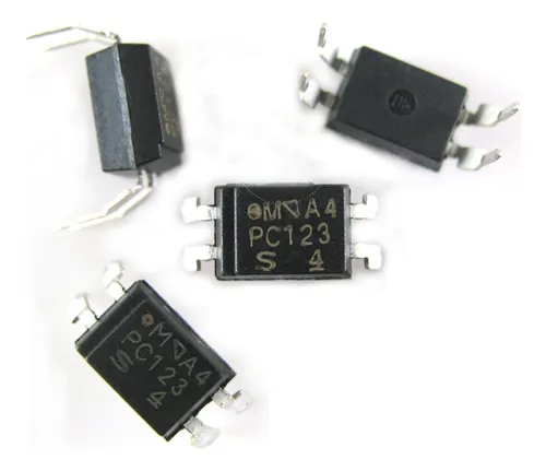
The PC123 pinout helps engineers connect the PC123 optocoupler. It shows how to use it in any circuit. Knowing the right pins stops wiring mistakes. It also keeps sensitive devices safe. The PC123 series has four pins. Each pin does a special job. Many people check the datasheet for more details. If you use the wrong pinout, the PC123 optocoupler can break. The circuit might not work right.
Engineers often look at PC123 and PC817 to pick an optocoupler for projects.
Key Takeaways
-
The PC123 optocoupler has four pins. Each pin has a job. Pins 1 and 2 go to the LED input. Pins 3 and 4 go to the output transistor. You must connect the pins the right way. This stops damage and helps it work right.
-
Always look at the PC123 datasheet for limits. Check things like forward voltage, current, and max ratings. This keeps the device safe and working well in your circuit.
-
PC123 equivalents like PC817 and TLP621 are similar. But they may have different current transfer ratios and voltage ratings. Always check datasheets before you swap parts.
-
The PC123 and PC817 have the same pinout. They also have close specs. You can use them in most projects the same way. Pick PC123 for steady work. Pick PC817 if you want to save money or if it is easier to find.
-
Use the PC123 optocoupler to keep signals apart. It can protect microcontrollers and help switch circuits safely. Add a current-limiting resistor and plan your PCB well. This makes it more reliable and cuts down noise.
PC123 Pinout
Diagram
The PC123 pinout shows how each pin connects inside the device. The PC123 has a simple 4-pin layout. This makes it easy to use in many circuits. The diagram below helps users see the correct order of the pins when looking at the front of the PC123 optocoupler.
      _________
     |         |
  1 -|         |- 4
  2 -|  PC123  |- 3
     |_________|
| Pin Number | Name | Function |
|---|---|---|
| 1 | Anode | LED Positive (+) |
| 2 | Cathode | LED Negative (–) |
| 3 | Emitter | Output Emitter |
| 4 | Collector | Output Collector |
Tip: Always check the PC123 pinout before soldering the device to a PCB. This prevents wiring mistakes and protects the circuit.
Pin Functions
Each pin on the PC123 has a special job. The PC123 optocoupler uses an LED and a phototransistor inside the package. The LED side connects to pins 1 and 2. The phototransistor side connects to pins 3 and 4.
-
Pin 1 (Anode): This pin connects to the positive side of the input signal. When current flows into this pin, the LED inside the PC123 lights up.
-
Pin 2 (Cathode): This pin connects to the negative side of the input signal. It completes the LED circuit.
-
Pin 3 (Emitter): This pin is the emitter of the output transistor. It usually connects to ground in the output circuit.
-
Pin 4 (Collector): This pin is the collector of the output transistor. It connects to the load or the positive voltage in the output circuit.
The PC123 pinout helps engineers match the right pins to the right parts of their circuit. Using the correct pin functions keeps the PC123 working safely and reliably.
Identification
Identifying the PC123 pinout on a real device is important. The PC123 package has a small notch or dot near pin 1. This mark helps users find the starting point for counting pins. The pins are numbered counterclockwise when looking at the top of the PC123 optocoupler.
Steps to identify the PC123 pinout:
-
Hold the PC123 so the text faces up.
-
Find the notch or dot near one corner. This is pin 1.
-
Count the pins counterclockwise: pin 1, pin 2, pin 3, and pin 4.
-
Match each pin to the diagram and table above.
Note: Always double-check the PC123 datasheet for the correct pinout. Some optocouplers may look similar but have different pin layouts.
The PC123 pinout is simple, but correct identification is key. This ensures the PC123 optocoupler works as expected in any project.
PC123 Optocoupler Datasheet
Electrical Specs
The PC123 optocoupler has an infrared LED and a phototransistor inside. The datasheet gives important numbers for using it. The input side uses a forward voltage of 1.2V and a forward current of 20mA. The output side can handle up to 80V between collector and emitter. The current transfer ratio, or CTR, tells how much current moves from input to output. The datasheet says the CTR can be from 50% to 600%. This depends on the model and test conditions. CTR helps engineers know what output current to expect from the input current. The PC123 works fast and stays steady in many circuits.
| Parameter | Typical Value |
|---|---|
| Forward Voltage (LED) | 1.2V |
| Forward Current (LED) | 20mA |
| Collector-Emitter Voltage | 80V |
| CTR (Current Transfer Ratio) | 50%–600% |
Note: Always look at the datasheet pdf for the right PC123 numbers for your project.
Maximum Ratings
The PC123 datasheet shows the highest safe limits. These limits keep the device from breaking. The LED can take up to 50mA forward current. The reverse voltage for the LED is 6V. The output transistor can handle 80V between collector and emitter. The collector current can go up to 50mA. The storage temperature can be from -55°C to +125°C. Going over these limits can hurt the PC123.
-
Forward Current (LED): 50mA max
-
Reverse Voltage (LED): 6V max
-
Collector-Emitter Voltage: 80V max
-
Collector Current: 50mA max
-
Storage Temperature: -55°C to +125°C
Engineers should always use the maximum ratings in the datasheet pdf to keep the PC123 safe.
Package Info
The PC123 comes in a small 4-pin DIP package. The datasheet shows the size and shape. The body is about 7.0mm by 6.5mm by 3.5mm. The pins fit standard PCBs. The small size makes it easy to use in many projects. The datasheet also has example circuits and notes. These help engineers use the PC123 optocoupler the right way.
The PC123 specs and package details make it a good choice for signal isolation and switching.
PC123 Equivalent Models
List of Equivalents
Many engineers want to find pc123 equivalents for their circuits. The pc123 series is a lot like other devices. These other choices help if you cannot get the original part. The table below shows some common pc123 equivalents. Each one can take the place of the pc123 in many uses.
| Equivalent Model | Manufacturer | Notes |
|---|---|---|
| PC817 | Sharp | Popular, similar specs |
| PC816 | Sharp | Lower CTR range |
| TLP621 | Toshiba | Higher isolation |
| TLP321 | Toshiba | Surface-mount option |
| TLP421 | Toshiba | High CTR |
| PC17K1 | Sharp | Similar to pc123 series |
| H11A817 | Fairchild | Widely used |
| SFH615A | Vishay | Good for replacements |
| PS2501-1 | Renesas | High reliability |
| PS2561-1 | Renesas | Compact package |
Engineers pick from this list when they need a good photocoupler.
Differences
The pc123 series and its equivalents are not always the same. These small changes can matter in some projects. One big thing to check is the current transfer ratio, or CTR. The pc123 series has a wide CTR, from 50% to 600%. Some, like PC817, also have a CTR from 50% to 600%. Others, like PC816, have a lower CTR. Voltage ratings are different too. The pc123 can handle up to 80V between collector and emitter. TLP621 and SFH615A can also handle 80V, but some, like PS2501-1, might have different limits.
Isolation voltage is another thing to look at. The pc123 series usually gives 5kV isolation. Some, like TLP621, give even more isolation. The package type can change too. TLP321 is a surface-mount part, but the pc123 series uses a DIP package.
Always check the datasheets before using a pc123 equivalent. This helps make sure the optocoupler works safely in your circuit.
PC123 vs. PC817
Pinout Comparison
The pinout for the pc123 and PC817 is almost the same. Both have four pins in a DIP package. Each pin connects to the same part inside the chip. Pin 1 is the anode. Pin 2 is the cathode. Pin 3 is the emitter. Pin 4 is the collector. This lets engineers swap them in most circuits without trouble.
| Pin Number | PC123 Function | PC817 Function |
|---|---|---|
| 1 | Anode | Anode |
| 2 | Cathode | Cathode |
| 3 | Emitter | Emitter |
| 4 | Collector | Collector |
The pinout for pc123 and pc817 is a perfect match. Engineers can use the same PCB for both chips.
Specs Comparison
The pc123 and PC817 have many features that are the same. But some specs are a bit different. The table below shows the main differences between them.
| Feature | PC123 | PC817 |
|---|---|---|
| Forward Voltage (LED) | 1.2V | 1.2V |
| Reverse Voltage (LED) | 6V | 6V |
| Forward Current (LED) | 50mA max | 50mA max |
| Collector-Emitter Voltage | 80V max | 80V max |
| Collector Current | 50mA max | 50mA max |
| Current Transfer Ratio | 50%–600% | 50%–600% |
| Isolation Voltage | 5kV RMS | 5kV RMS |
| Package | 4-pin DIP | 4-pin DIP |
Both chips use the same forward and reverse voltage for the LED. The current transfer ratio, or CTR, is also the same. This means the output current matches the input current in both. Both chips give 5kV RMS isolation. This keeps circuits safe from high voltages.
Some PC817 models may have a different CTR range. This depends on who made the chip. The pc123 usually has steady specs. Engineers should check the datasheet for the right numbers.
Note: The specs for pc123 and PC817 are so close. Most designs can use either one.
Applications
Engineers use both pc123 and PC817 for many of the same jobs. These optocouplers are good for signal isolation and switching. They also help microcontrollers talk to other parts. The strong isolation keeps sensitive parts safe from high voltage.
-
Microcontroller input and output isolation
-
Power supply feedback circuits
-
Switching power supplies
-
Signal transmission between different voltage levels
-
Home appliance control boards
The pc123 is great for circuits that need a wide CTR. It works with many input and output currents. The PC817 also works well in these uses. Some engineers pick pc123 for its steady performance.
Engineers pick pc123 when they want reliable CTR and strong isolation. PC817 is good for saving money or if it is easier to find.
The choice between pc123 and pc817 often depends on what is in stock. Small spec differences matter in some projects. Both chips work well for most optocoupler needs.
PC123 Applications
Use Cases
Engineers use the pc123 in lots of projects. This optocoupler helps keep signals apart in a circuit. It protects microcontrollers from high voltages. Many people put the pc123 in power supply feedback circuits. It is also found in switching power supplies and control boards for home appliances. Some designers use the pc123 to send signals between circuits with different ground levels. This keeps sensitive parts safe from electrical noise.
Common use cases for the pc123:
-
Microcontroller input and output isolation
-
Power supply feedback
-
Signal transmission between high and low voltage sections
-
Home appliance control
-
Industrial automation systems
Example Circuits
The pc123 works in both simple and complex circuits. One easy example uses the pc123 to keep a microcontroller safe from a relay driver. The LED side connects to a digital output pin. The transistor side connects to the relay circuit. When the microcontroller sends a signal, the pc123 turns on the relay safely.
Microcontroller Output ----[Resistor]----|>|---- Pin 1 (pc123)
                                         |      Pin 2 (pc123) ---- GND
                                         |
Relay Driver Circuit ---- Pin 4 (pc123)
                       |
                       Pin 3 (pc123) ---- GND
This setup keeps the microcontroller safe from voltage spikes in the relay circuit.
Tips
Engineers should always read the datasheet before using the pc123. They need to match the input and output currents to the pc123 ratings. A current-limiting resistor on the LED side stops damage. Good PCB layout helps lower noise and gives better isolation. If a project needs a replacement, engineers can use a pc123 equivalent, but they should check the datasheets first.
-
Use a resistor to limit LED current.
-
Keep input and output grounds separate.
-
Check the pc123 orientation before soldering.
-
Test the circuit with a multimeter before powering up.
Using the pc123 carefully makes circuits safer and more reliable.
The PC123 optocoupler has an easy-to-understand pinout. It also has strong electrical features and many similar models. Engineers can use tables to check what each pin does. These tables also help compare the PC123 to other devices. It is important to read the datasheet before building a circuit. This keeps the design safe and correct. The PC123 is good for projects that need steady performance. The PC817 is better if you want to save money or find parts easily.
FAQ
What does the PC123 optocoupler do?
The PC123 optocoupler keeps two circuits separate. It uses light to send signals from one side to the other. This helps protect sensitive parts from high voltage or noise.
Can you use PC817 instead of PC123?
Yes, engineers often use PC817 as a replacement for PC123. Both have similar pinouts and electrical features. Always check the datasheet to make sure the specs match your project.
How do you connect the PC123 in a circuit?
Connect the input signal to pins 1 (anode) and 2 (cathode). Connect the output side to pins 3 (emitter) and 4 (collector). Use a resistor with the LED to limit current.
What is the CTR in the PC123 datasheet?
CTR stands for Current Transfer Ratio. It shows how much output current you get for a given input current. For PC123, CTR ranges from 50% to 600%, depending on the model.
Where do you find the pin 1 mark on the PC123?
A small dot or notch marks pin 1 on the PC123 package. Hold the chip with the text facing up. The mark helps you find the correct starting point for pin numbering.
Written by Jack Elliott from AIChipLink.
AIChipLink, one of the fastest-growing global independent electronic components distributors in the world, offers millions of products from thousands of manufacturers, and many of our in-stock parts is available to ship same day.
We mainly source and distribute integrated circuit (IC) products of brands such as Broadcom, Microchip, Texas Instruments, Infineon, NXP, Analog Devices, Qualcomm, Intel, etc., which are widely used in communication & network, telecom, industrial control, new energy and automotive electronics.
Empowered by AI, Linked to the Future. Get started on AIChipLink.com and submit your RFQ online today!


