How to Design a 13V 2A PSU Circuit for Handheld Rigs
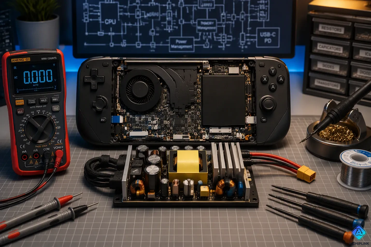
Build your 13v 2a psu circuit for handheld rigs around an STR2012 or STR2013 hybrid regulator. This voltage regulator ic combines a switch-mode power supply and a fixed output on one die. Add a thyristor-zener crowbar, and it protects your radio from overvoltage.
Four decisions shape the design. First, size the front-end rectification. Second, choose the IC. Third, set the crowbar. Fourth, plan the layout.
The 13 v rail suits handheld amateur radio rigs, VHF/UHF portable PMRs, and other ham radio rigs. A steady feed keeps them happy. Plan each step, and you get a quiet, safe line at the rig.
Key Takeaways
-
Pick a transformer and capacitor that are a little bigger than you need. This gives the regulator enough extra room to work well.
-
Pick the STR2013 to get a steady 13V output and use fewer external parts.
-
Set the crowbar trigger just above 13V. This keeps your rig safe from too much voltage.
-
Use star grounding and a short high-current loop to keep the output quiet.
-
Check the crowbar trip point before you hook up your radio.
Front-End Power Supply Design
The front end moves energy in four stages. A mains transformer steps the line down. A bridge rectifier turns the AC into pulsing DC. A smoothing capacitor stores charge and flattens the pulses. The regulation stage then holds a steady output. Each stage passes its result to the next, so a weak link here shows up as hum or sag at the rig.
Transformer and Bridge Rectifier
Pick a transformer with a secondary that leaves headroom above your target. A full diode bridge with roughly 10,000 µF of smoothing yields about 17 VDC at no load. That figure is the no-load voltage, the level you measure with nothing drawing current. The same rail drops under a 3–4 A draw. This drop comes from winding resistance and diode losses.
The STR regulator needs that headroom. It holds a fixed output while its input stays above a minimum level. Too small a transformer pushes the input toward that floor during peaks. Size the secondary generously, and the regulator keeps control through every load swing.
Smoothing Capacitor Sizing
Ripple is the small sawtooth left on the DC after rectification. More capacitance means less ripple. The capacitor value is directly proportional to the load current: doubling the load current requires doubling the capacitance to keep the ripple voltage the same. The general relation is C = I_load × Δt / V_ripple, where Δt is the discharge interval and V_ripple is the ripple voltage.
For a full-wave rectifier, the working form is C = I_load / (4 × f × Vpp). Here C is in farads, I_load in amperes, f is the line frequency in hertz, and Vpp is the peak-to-peak ripple in volts. A 2 a load with a 50 Hz line and a modest ripple target lands near the 10,000 µF figure above. Check the capacitor's ripple current rating too, because a large reservoir cap carries heavy charging pulses.
Building the 13V 2A PSU Circuit for Handheld Rigs
Why the STR Regulator Beats Linear Options
You have several ways to hold a steady rail. Each option fits a different job, and the table below shows where the STR2012/STR2013 family sits next to the classic linear parts.
| Regulator | External component count | Input voltage range |
|---|---|---|
| STR2012/STR2013 | Fewer — this hybrid power IC integrates a switch-mode power supply and avoids the fair number of external parts typical of linear designs | Accepts relatively high input voltages; raw input specified as 18 to 35 V |
| LM317, LM350, LM723 | Fairly high — these linear regulators are invariably associated with a fair number of external components | Not stated in the source; treat it as a design factor to weigh |
The LM317 and LM350 suit low-current bench work where simplicity matters. The LM723 gives you flexible control for custom builds. The STR parts win when board space is tight. Sanken Electric packs the switch-mode stage and a fixed output into a 5-pin package. That integration keeps the 13v 2a psu circuit for handheld rigs compact.
Choosing the STR2013 for 13V Output
The STR family offers 5.1 V, 12 V, 13 V, 15 V, and 24 V variants, all rated at 2 A. The STR2012 targets 12 V. The STR2013 targets 13 V. Most handheld rigs run on voltages between 12.6v and 13.8v. The 13 V part lands inside that window, so builders usually pick the STR2013 over the STR2012.
Check the ratings before you commit. The STR2013 carries a 2a output current rating, with a 3.0 A pulse capability. Its DC input rating reaches 45 V, well above the 18 to 35 V raw input you will feed it. Efficiency sits near 80%, and ripple rejection reaches about 45 dB. Those figures explain why the part holds a clean 13 v rail under load.
The hybrid voltage regulator ic also saves you the heatsink math of a linear pass stage. A linear regulator burns the difference between input and output as heat. The switch-mode power supply inside the STR2013 chops and transforms instead, so it wastes less power. That matters at 2 a continuous draw.
One caution: the STR2013 still needs heatsink mounting. Its power dissipation rating is relatively high, and the package expects a thermal path. Plan the mounting before you lay out the board.
The integrated design pays off in size. A discrete switcher needs a controller, a switch, and a feedback network. The STR2013 needs only its input and output capacitors, the inductor, and the crowbar parts. That short list keeps the 13v 2a psu circuit small enough for a handheld enclosure. You get a quiet 13v output without a sprawling board.
Crowbar Protection for the 13v/2a PSU
A regulator can fail short. When it does, the full input voltage lands on your rig. A crowbar sits across the output and waits for that moment. The name comes from the old trick of dropping a metal bar across a supply rail to kill it fast.
A crowbar circuit differs from a clamp: once triggered, it pulls the voltage below the trigger level, usually close to ground, whereas a clamp merely prevents the voltage from exceeding a preset level. Consequently, a crowbar does not automatically resume normal operation when the overvoltage is removed—power must be fully removed to reset it.
That behavior suits a 13v/2a power supply well. You want a hard shutdown, not a gentle nudge. The crowbar is the key safeguard for an expensive handheld rig. A failed pass stage can send raw input straight to your radio. The crowbar stops that event before it reaches the connector.
Thyristor and Zener Selection
The crowbar needs two active parts. A zener diode senses the rail. A thyristor, also called an SCR, does the shunting. Pick the zener first. Its breakdown voltage must sit slightly above the normal output voltage. The classic example uses a 5.2 V zener for a 5 V load. Scale that logic to your rail: choose a zener that breaks down just above 13 V.
Then pick the thyristor. It must handle the crowbar current for the whole overvoltage event. Check its surge rating against your fuse. The SCR also needs a gate current low enough for the zener to fire it. Read both datasheets side by side before you order parts.
Setting the Trigger Threshold
Set the threshold just above the normal 13 v output. Too low, and normal ripple trips the crowbar. Too high, and your rig sees damage before the shunt fires. A small trim pot in the zener leg lets you fine-tune the trip point on the bench.
The trigger sequence runs in six steps:
-
A zener diode is chosen with a breakdown voltage slightly above the load's normal operating voltage (e.g., 5.2 V for a 5 V load).
-
While the supply stays at or below the normal voltage, the zener does not conduct and the load operates normally.
-
When the output voltage rises to the zener's breakdown voltage, the zener conducts and feeds current into the thyristor (SCR) gate.
-
The gate current fires the thyristor, which then conducts heavily and creates a low-impedance path to ground.
-
This path draws excess current through the fuse, causing the fuse to blow and disconnect the supply from the load.
-
With the fuse open, the load is de-energized and protected from the overvoltage; the cheap fuse is replaced to restore operation.
Test the trip point with a variable supply before you connect a radio. Raise the output slowly and watch for the shunt. Then confirm the fuse opens. This step protects your handheld amateur radio rigs, your vhf/uhf portable pmrs, and any other ham radio rigs on your bench. The 13v 2a psu circuit earns its trust here, not at the drawing board.
Supporting Components and Layout
Reverse Polarity, Heatsinking, and Ripple Rejection
A wrong-way connection can kill your board before the regulator even runs. Add reverse polarity protection at the input. The table below shows the common methods and where each one fits.
| Method | Key Characteristics | Suitability for 13V 2A |
|---|---|---|
| Full-wave bridge rectifier | Fixes polarity by itself; drops 1.5V–2V; wastes a lot of power at higher currents | Poor for 2A because of the big drop and heat |
| Schottky diode (series) | Simple; forward drop usually under 0.5V; best for low or medium current | Good fit for 2A |
| P-channel MOSFET | Low voltage drop; avoids diode loss; needs a proper gate rating (e.g., a 20V gate spec allows direct gate-to-ground) | Suitable when cutting the drop matters |
| Diode + fuse (reverse parallel) | Almost no voltage loss; the fuse blows on a reverse connection | A workable simple option |
A series Schottky diode suits a 2 a draw well. Its low forward drop wastes little power. A P-channel MOSFET works when you want to cut that loss further.
Next, size the heatsink. Follow these steps:
-
Work out the worst-case power dissipation using the highest input voltage and the highest load current.
-
Find the highest ambient temperature at the regulator's mounting spot, using the temperature inside the enclosure.
-
Take the manufacturer's maximum junction temperature and add a safety margin.
-
Figure out the highest junction-to-ambient thermal resistance you can allow.
-
Subtract the package and interface thermal resistances to get the heatsink rating you need.
Good ripple rejection keeps hum off the 13 v rail. The STR2013 already rejects about 45 dB, so the output stays quiet.
Coil Selection and Star Grounding
The coil, or inductor, carries the switching current. Pick one rated for the peak current with some room to spare. A coil that saturates makes the switcher noisy and hot.
Star grounding keeps the 13v 2a psu circuit stable. Run each ground return to a single point. Keep the high-current loop short. This layout choice lowers noise on the output and protects the regulator's feedback sense.
The STR2013 gives you a compact, reliable 13V 2A supply. Its fixed output voltage holds steady, and the hybrid IC's high power dissipation rating keeps it cool under load. The crowbar adds a safeguard: a thyristor fires when the rail climbs too high and shorts the supply to protect your radio.
Four choices carry the design. Size the front end for headroom. Pick the STR2013 for its 13V output and few external parts. Set the crowbar threshold just above normal output. Plan star grounding for a quiet rail.
Check your rig's needs before you build, then test the trip point. Your careful work pays off with a supply you can trust.

Written by Jack Elliott from AIChipLink.
AIChipLink, one of the fastest-growing global independent electronic components distributors in the world, offers millions of products from thousands of manufacturers, and many of our in-stock parts is available to ship same day.
We mainly source and distribute integrated circuit (IC) products of brands such as Broadcom, Microchip, Texas Instruments, Infineon, NXP, Analog Devices, Qualcomm, Intel, etc., which are widely used in communication & network, telecom, industrial control, new energy and automotive electronics.
Empowered by AI, Linked to the Future. Get started on AIChipLink and submit your RFQ online today!
Frequently Asked Questions
Does the crowbar reset itself after it fires?
No. Once the thyristor fires, it keeps conducting and holds the rail near ground. You must remove input power to reset it. Then replace the blown fuse before you power the rig again.
Why pick the STR2013 instead of the STR2012?
The STR2012 targets 12 V. The STR2013 targets 13 V. Most handheld rigs run between 12.6 V and 13.8 V, so the 13 V part sits inside that window. Builders usually choose it for that reason.
How much smoothing capacitance do I need?
A 2 A load on a 50 Hz line with a modest ripple target lands near 10,000 µF. That reservoir yields about 17 VDC at no load. Check the capacitor's ripple current rating too, because it carries heavy charging pulses.
Can I skip the heatsink on the STR2013?
No. The part still needs a thermal path. Work out worst-case dissipation from the highest input voltage and load current. Then size the heatsink from the junction-to-ambient limit. Plan the mounting before you lay out the board.
What keeps hum off the 13 V rail?
The STR2013 rejects about 45 dB of ripple on its own. Add star grounding and a short high-current loop. Together they lower noise and protect the regulator's feedback sense. That combination delivers quiet power to your rig.