In circuit diagrams, the potentiometer symbol represents a three-terminal device used to control voltage or resistance. It typically features a resistor symbol with an arrow crossing it, indicating adjustable functionality. Recognizing this symbol is essential for anyone working with electronic circuits.
Potentiometers play a crucial role in modern electronics. The global market for these components, valued at $1.2 billion in 2022, continues to grow at a steady 5.5% annual rate. This trend reflects their widespread use in consumer electronics, automotive systems, and precision instruments. Devices like smartphones and gaming consoles increasingly rely on advanced potentiometers to enhance performance and functionality.
Key Takeaways
-
Learn potentiometer symbols in circuit diagrams. These symbols show adjustable parts in electronic designs.
-
Tell apart ANSI and IEC potentiometer symbols. Knowing the difference prevents mistakes and helps read circuits correctly.
-
Use potentiometers to control circuits better. They let you change voltage and resistance to improve devices.
-
Follow tips to read circuit diagrams easily. Knowing common symbols and links helps you fix and understand circuits.
-
Use potentiometer symbols for testing and building. These symbols help engineers test ideas and improve circuit designs.
What Is a Potentiometer?
A potentiometer is a fundamental electronic component used to control electrical resistance and voltage in a circuit. It is a type of variable resistor with three terminals, enabling users to adjust resistance levels manually. Potentiometers are widely used in various applications, from audio equipment to industrial machinery, due to their versatility and simplicity.
Function of a Potentiometer
Potentiometers perform two primary functions in electrical circuits: acting as a variable resistor and serving as a voltage divider. These components consist of a resistive strip connected to two terminals and a movable wiper connected to the third terminal. By sliding the wiper along the resistive strip, the resistance between the terminals changes. This adjustment allows users to control current flow and voltage levels effectively.
For example, in audio devices, potentiometers regulate volume by altering the resistance in the circuit. This functionality makes them indispensable in applications requiring precise control over electrical parameters. According to technical documentation, potentiometers are essential for fine-tuning circuits, ensuring optimal performance in devices like amplifiers and signal processors.
Types of Potentiometers
Potentiometers come in various types, each designed for specific applications. The most common types include:
-
Rotary Potentiometers: These are the most widely used and feature a rotating knob to adjust resistance. They are commonly found in audio equipment and consumer electronics.
-
Linear Potentiometers: These operate by sliding a wiper along a straight resistive strip. They are often used in industrial machinery and measurement instruments.
-
Digital Potentiometers: These modern variants use digital signals to adjust resistance. They are ideal for applications requiring precise and automated control.
The table below highlights an authoritative source defining potentiometers:
| Source | Description |
|---|---|
| The Authoritative Dictionary of IEEE Standards Terms (IEEE 100) | A recognized standard reference for definitions in electronics, including potentiometers. |
Understanding the types of potentiometers helps engineers and hobbyists select the right component for their circuit design. Each type offers unique advantages, making them suitable for different scenarios.
Potentiometer Symbols in Circuit Diagrams
ANSI Potentiometer Symbol
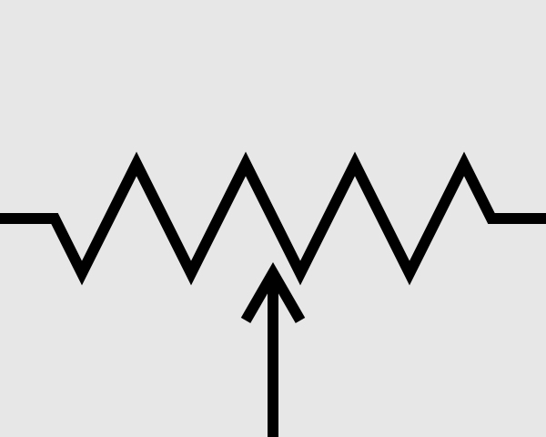
The ANSI standard represents a potentiometer with a distinct symbol. It features two straight lines connected by zigzag lines, symbolizing the resistive element. An arrow intersects the zigzag lines, indicating the adjustable wiper arm. This design highlights the potentiometer's role as a variable resistor, allowing users to modify resistance or voltage in a circuit.
The simplicity of the ANSI potentiometer symbol makes it widely recognized in the United States. Engineers and technicians rely on this representation to identify potentiometers in circuit diagrams quickly. Its design emphasizes functionality, ensuring clarity in schematic layouts.
IEC Potentiometer Symbol
The IEC standard uses a different approach to depict potentiometers. Instead of zigzag lines, it employs a rectangle placed between two straight lines. Similar to the ANSI symbol, an arrow crosses the rectangle to signify the adjustable wiper arm. This design aligns with the IEC's focus on uniformity and simplicity in graphical representations.
The IEC potentiometer symbol is commonly used in Europe and other regions that follow international standards. Its clean and straightforward design ensures compatibility across various industries. Engineers working with IEC-compliant circuit diagrams can easily identify potentiometers and their adjustable nature.
| Standard | Description |
|---|---|
| IEC 60617 | Covers the graphic symbols used for electrical components in circuit diagrams. |
| IEC 61131-3 | Pertains to ladder-logic symbols. |
| AS 1102 | Based on IEC 60617, but has been withdrawn without replacement. |
Differences Between ANSI and IEC Symbols
The ANSI and IEC standards differ significantly in their representation of potentiometers. The ANSI symbol uses zigzag lines to depict the resistive element, while the IEC symbol opts for a rectangle. Both symbols include an arrow to indicate the variable wiper arm, but their overall designs reflect different regional preferences.
| Standard | Symbol Representation |
|---|---|
| ANSI | Two straight lines with zigzag lines in between |
| IEC | A rectangle between two straight lines |
Understanding these differences is crucial for engineers and hobbyists working with circuit diagrams. Misinterpreting a potentiometer symbol could lead to errors in circuit design or troubleshooting. Familiarity with both standards ensures accurate identification of components, regardless of the schematic's origin.
Tip: When analyzing circuit diagrams, always check the standard used in the schematic. This practice helps avoid confusion and ensures proper interpretation of common potentiometer symbols.
How to Interpret Potentiometer Symbols
Identifying Potentiometer Symbols
Potentiometer symbols in circuit diagrams represent a variable resistor with adjustable functionality. Engineers and hobbyists often encounter two main standards: the American Standard (ANSI) and the International Standard (IEC). Each uses distinct graphical representations to depict the potentiometer's structure and connections.
The American Standard symbol features a zigzag line resembling a resistor, with an arrow crossing it. This arrow signifies the wiper's ability to adjust resistance. In contrast, the International Standard symbol uses a rectangular box with two terminals on either side and an arrow in the center. These symbols highlight the potentiometer's role as a variable resistor and its three-terminal design.
To interpret these symbols effectively, understanding their components is essential. The table below outlines the key elements:
| Component | Description |
|---|---|
| Resistor Line | Represents the fixed resistive part of the potentiometer. |
| Arrow | Indicates the wiper that adjusts resistance. |
| Three Terminals | Two connect to the resistor ends, one to the wiper. |
Recognizing these elements helps users identify potentiometers in circuit diagrams and understand their adjustable nature.
Common Variations in Potentiometer Symbols
Potentiometer symbols may vary depending on the circuit diagram's origin or the designer's preferences. While ANSI and IEC standards dominate, slight modifications can occur. These variations often include changes in the arrow's placement or the shape of the resistive element.
Some diagrams may depict the resistor line as curved rather than zigzagged, while others might use a simplified rectangle without an arrow. These differences do not alter the potentiometer's function but can affect interpretation during analysis. Engineers must remain vigilant when tracing circuits to ensure accurate identification of components.
Unordered lists can help summarize methodologies for identifying these variations:
-
American Standard Symbol: Characterized by a zigzag line resembling a resistor symbol, with an arrow above it.
-
International Standard Symbol: A rectangular box with two terminals on either side and an arrow in the center.
Familiarity with these variations ensures clarity during circuit analysis and prevents errors in design or troubleshooting.
Practical Tips for Reading Circuit Diagrams
Reading circuit diagrams requires a systematic approach to understanding symbols and connections. Potentiometer symbols, like other components, demand attention to detail and practice. Several strategies enhance the ability to interpret these symbols accurately:
-
Familiarize yourself with common circuit symbols. Resources like Circuit Diagram Symbols provide comprehensive guides for beginners.
-
Understand the connections between components. Potentiometers typically connect to resistive elements and wipers, forming adjustable circuits.
-
Practice with real-world examples to enhance comprehension. Technical literature, such as Understanding Electrical Schematics: A Comprehensive Guide, emphasizes the importance of hands-on experience.
Tracing circuits becomes easier with consistent practice and exposure to diverse schematic designs. Engineers and hobbyists can improve their analysis skills by applying these tips to real-world scenarios.
Applications of Potentiometer Symbols in Circuit Design
Examples in Circuit Design
Potentiometer symbols play a vital role in designing circuits for various applications. Engineers use these symbols to represent adjustable resistors in printed circuit boards. For instance, audio amplifiers often include potentiometers to control volume levels. The potentiometer symbol in these designs indicates the component's ability to adjust resistance and fine-tune sound output.
In lighting systems, potentiometers help regulate brightness by modifying voltage levels. Circuit board symbols for potentiometers guide designers in placing these components correctly. This ensures smooth operation and precise control over light intensity. Additionally, potentiometers are essential in sensor calibration circuits. They allow users to adjust sensitivity levels, ensuring accurate readings from temperature or pressure sensors.
Understanding how potentiometers work enables engineers to optimize circuit performance. By interpreting potentiometer symbols accurately, they can design circuits that meet specific requirements, whether for consumer electronics or industrial machinery.
Troubleshooting with Potentiometer Symbols
Troubleshooting potentiometer-related issues requires a systematic approach. Engineers often rely on technical documentation to resolve problems effectively. Common methodologies include:
-
Checking Connection Tightness: Loose connections can cause unstable resistance values. Inspecting the potentiometer's connections ensures reliable performance.
-
Identifying Short Circuits: Shorts can disrupt functionality and lead to overheating. Using a multimeter helps detect and eliminate these issues.
-
Inspecting the Potentiometer and Surrounding Components: Mechanical wear or damage can affect resistance changes. Testing the potentiometer and nearby components ensures proper operation.
These steps highlight the importance of understanding potentiometer symbols during troubleshooting. Accurate interpretation of circuit board symbols helps engineers pinpoint issues and restore functionality quickly.
Prototyping and Testing Scenarios
Prototyping and testing scenarios often involve potentiometer symbols to represent adjustable components. During prototyping, engineers use potentiometers to test circuit behavior under varying resistance levels. This process helps identify optimal configurations for printed circuit boards.
In testing scenarios, potentiometers allow users to simulate real-world conditions. For example, adjusting a potentiometer in a prototype audio system helps evaluate sound quality at different volume levels. Similarly, testing sensor circuits with potentiometers ensures accurate calibration before final production.
Knowing how potentiometers work enhances the prototyping process. Engineers can interpret potentiometer symbols to design flexible circuits that accommodate adjustments during testing. This approach ensures the final product meets performance standards and user expectations.
Recognizing the potentiometer symbol in circuit diagrams is essential for understanding adjustable components. This knowledge empowers engineers and hobbyists to interpret schematics accurately and design circuits that meet specific requirements. By mastering potentiometer symbols, individuals can troubleshoot issues effectively and optimize circuit performance.
Note: Familiarity with these symbols enhances the ability to analyze and prototype circuits, ensuring precision in electronic designs.
FAQ
What is the purpose of the arrow in potentiometer symbols?
The arrow represents the adjustable wiper arm. It indicates the ability to modify resistance or voltage by moving the wiper along the resistive element. This feature makes potentiometers versatile components in circuit design.
How can someone differentiate between ANSI and IEC potentiometer symbols?
ANSI symbols use zigzag lines to depict the resistive element, while IEC symbols use a rectangle. Both include an arrow to signify adjustability. Engineers should check the schematic's standard to avoid misinterpretation.
Are potentiometer symbols the same in all circuit diagrams?
No, potentiometer symbols vary based on regional standards like ANSI or IEC. Designers may also use slight modifications, such as curved lines or simplified rectangles. Familiarity with these variations ensures accurate identification.
Can potentiometer symbols help in troubleshooting circuits?
Yes, potentiometer symbols guide engineers in locating adjustable components. They help identify issues like loose connections or short circuits. Accurate interpretation simplifies troubleshooting and ensures efficient repairs.
Why are potentiometer symbols important in prototyping?
Potentiometer symbols represent adjustable components used to test circuit behavior. Engineers rely on these symbols to simulate real-world conditions and optimize designs during prototyping. This ensures the final product meets performance standards.
Written by Jack from AIChipLink.
AIChipLink, one of the fastest-growing global independent electronic components distributors in the world, offers millions of products from thousands of manufacturers, and many of our in-stock parts is available to ship same day.
We mainly source and distribute integrated circuit (IC) products of brands such as Broadcom, Microchip, Texas Instruments, Infineon, NXP, Analog Devices, Qualcomm, Intel, etc., which are widely used in communication & network, telecom, industrial control, new energy and automotive electronics.
Empowered by AI, Linked to the Future. Get started on AIChipLink.com and submit your RFQ online today!


