What is a Capacitor?
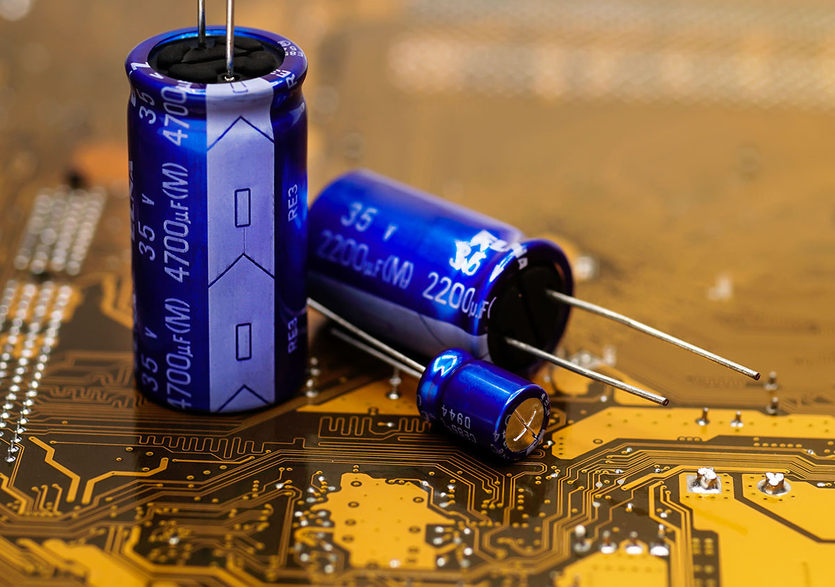
A capacitor is an electronic component widely used in various electrical and electronic circuits. It is designed to store and release electrical energy, acting as a temporary reservoir or “energy buffer” within a circuit. Compared to a typical battery, a capacitor can store very small amounts of energy, such as 10,000 times smaller, which is still useful for many devices and circuits.
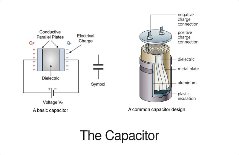
It is made up of two conducting plates and a dielectric, which is an insulating substance. An electric field forms across the dielectric when a voltage is applied between the plates, which causes an electrical charge to build up. Main purpose of types of capacitors is to store charge. Electrons build up on one plate of a capacitor when it is linked to a power source, while an opposite but equal charge builds up on the other plate. The surface area, spacing, and kind of dielectric material all affect how much charge a capacitor can hold. The unit of measurement for this is farads (F).
Purpose of Capacitor Symbol in Electrical Schematics & Diagrams
Types of Capacitors You should know
| Type of Capacitor | Subcategories | Description |
| Ceramic Capacitors | Class 1: NP0, C0G Capacitor |
Very stable, minimal change in capacitance with temperature. Used in timing and precision applications. |
| Class 2: X7R Capacitor |
Good stability, suitable for bypass and decoupling applications over a wider temperature range. | |
| Class 2: Y5V Capacitor |
High capacitance value, significant capacitance change with temperature. Used where size and cost are critical. | |
| Class 2: Z5U Capacitor |
Used for bypass and decoupling; not suitable where tight capacitance tolerance is needed. | |
| Electrolytic Capacitors | Aluminum Electrolytic |
High capacitance, polarized. Ideal for power supply filters and audio amplifiers. |
| Tantalum Electrolytic |
Higher stability and reliability than aluminum, polarized. Used in medical and military applications. | |
| Niobium Electrolytic |
Similar to tantalum, cost-effective, and used in various electronic applications. | |
| Film Capacitors | Polyester Film (Mylar) |
Good dielectric strength, used in coupling and decoupling applications. |
| Polypropylene Film (PP) |
Excellent electrical properties, used in high-frequency and power applications. | |
| Polystyrene Film (PS) | Low cost, high stability, used in filters and timing circuits. | |
| Polyethylene Naphthalate (PEN) |
High temperature and frequency performance, suitable for demanding environments. | |
| Super Capacitors | Double-layer (EDLC) |
Used for rapid charge and discharge cycles such as in-memory backup systems. |
| Pseudo Capacitors |
Combines capacitor-like and battery-like properties for energy storage and high-power applications. | |
| Variable Capacitors | Air Variable | Manually adjustable, used in radio tuning and frequency adjustment. |
| Trimmer Capacitors |
Small, variable capacitors for device tuning during manufacturing or in-field adjustments. | |
| Vacuum Variable |
High voltage, stable tuning applications, used in high power and radio frequency systems. |
Capacitor Symbols
Now that you know the many types of capacitors, let’s discuss what a capacitor symbol is and its types! The symbol generally used to represent a capacitor in electronic circuit diagrams combines two parallel lines with a gap between them. It varies according to the type;
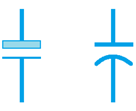
1. Fixed Capacitor Symbol

The symbol of a fixed capacitor is typically represented as two parallel horizontal lines with a space between them.
2. Polarized Capacitor Symbol
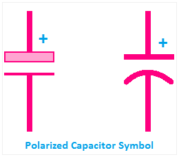
The symbol of a polarized capacitor includes a straight line and a curved line. The curved line represents the negative terminal, often indicated with a minus (-) sign or a specific marking on the capacitor. The straight line represents the positive terminal, typically the longer lead on the physical capacitor.
3. Variable Capacitor Symbol

The symbol for a variable capacitor in circuit diagrams is typically represented as two parallel lines with an arrow indicating the adjustable portion.
4. Electrolytic Capacitor Symbol
The symbol for an electrolytic capacitor is either two parallel lines or a straight line and a curved as shown in the image
5. Bipolar Capacitor Symbol

The symbol for a bipolar capacitor resembles a non-polar capacitor symbol in structure and can be connected to a circuit in any direction.
6. Trimmer Capacitor Symbol

A commonly used symbol for a trimmer capacitor is two parallel lines with a diagonal line in between, indicating the adjustable nature of the capacitor.
7. Feed Through Capacitor Symbol

The symbol for a feedthrough capacitor is usually represented as a capacitor with a straight line passing through it. This line represents the electrical connection or feedthrough between the two sides of the capacitor.
8. Voltage-Dependent Capacitor Symbol

One commonly used symbol for a voltage-dependent capacitor is a regular capacitor symbol with an arrow or a curved line pointing into it, indicating the dependency on the applied voltage.
9. Temperature-Dependent Capacitor Symbol

You can represent the temperature-dependent capacitor symbol by adding a temperature coefficient symbol to the regular capacitor symbol. The temperature coefficient represents the change in capacitance with respect to temperature.
Different Standards for Capacitor Symbols
| Standard | Region/Country | Non-Polarized Capacitors Description | Polarized Capacitors Description | Visual Notes/Identifiers |
| IEC | International | Two straight, parallel lines | One straight line and one curved line, indicate polarity | Simple and uniform lines; widely recognized in Europe |
| ANSI | United States | Two straight, parallel lines | Lines can be straight or curved with a plus (+) sign on the positive side | Clear polarity indication, common in the US |
| JIS | Japan | Two straight, parallel lines | Often marked with polarity, using straight or slightly modified lines | Polarity is often more explicitly marked than in IEC/ANSI |
| GOST | Russia | Similar to IEC but may include slight variations | Explicit polarity markings, possibly using different symbols | Unique elements that cater to Russian engineering standards |
| GB | China | Two straight, parallel lines, closely following IEC | Slight variations from the IEC style, with clear polarity indications | Adaptations may reflect specific Chinese documentation practices |
How to Read Capacitor Symbols?
You should be able to read a capacitor symbol to understand electronic circuit diagrams and schematics. Here’s the procedure to do so:
1. Know the Units of Measurement
Capacitance is measured in Farads (F), but in practice, capacitors are typically rated in smaller units such as microfarads (μF), nanofarads (nF), or picofarads (pF). Familiarize yourself with these units to interpret the values correctly.
2. Find the Capacitance
Numerical digits represent the capacitance value on the capacitor symbol. Look for a number that indicates the capacitance value. The number may be followed by a letter code indicating the unit of measurement.
3. Search for Tolerance Value
All capacitors have a tolerance that specifies the maximum allowable deviation from the stated capacitance value. This tolerance is represented by a percentage or a code on the symbol. The tolerance values can be anything, such as ±5%, ±10%, ±20%, or more. For instance, If you find “104K” on the symbol, the letter “K” represents a tolerance of ±10%.
4. Find the Voltage Rating
Capacitors also have a voltage rating, indicating the maximum voltage they can safely handle. The voltage rating is usually represented as a number followed by a unit such as volts (V) or kilovolts (kV). For instance, If you see “25V” on the symbol, the capacitor can handle a maximum voltage of 25 volts.
5. Look for a Positive or Negative Sign
Some capacitors, particularly polarized electrolytic and tantalum capacitors, have a polarity. They must be connected in the correct direction, or they may fail or even explode. The positive and negative terminals are indicated on the symbol using different markings, such as a plus sign (+) or a minus sign (-).
How Capacitor Works?
As we all know, metals are made of positively and negatively charged particles which make them neutral. However, when an electric field is applied, the electrons from the positive plate or side will start moving toward the negative plate. However, the dielectric between both plates doesn’t allow the electrons to pass through, resulting in electron accumulation on one plate.
The capacitor stores electrical energy in the form of the accumulated charge on its plates. The amount of charge stored is directly proportional to the applied voltage and the capacitance of the capacitor. The equation is given as follows:
- Q = CV relates the charge (Q) stored in the capacitor to the capacitance (C) and voltage (V) applied.
When the capacitor is connected to a circuit, such as a load or another component, it can release the stored energy. This is known as discharging.
Applications
Here are some applications of a capacitor:
• Energy storage in power supply circuits to provide a stable source of energy.
• Coupling and decoupling capacitors block DC and allow AC signals to pass.
• Filtering and smoothing of electrical signals to remove noise and ripples.
• Motor starting and phase-shifting in electric motors and HVAC systems.
FAQs
1. Why is the Capacitor Symbol important in Circuit Diagrams?
The capacitor symbol is vital in circuit diagrams as it represents the location of a component called a capacitor in a circuit. Capacitors typically store and release electrical energy and are an important circuit part.
2. Why are there different Symbols for Different Types of Capacitors?
Every capacitor has a different capacitance and voltage rating, so using different symbols for different types of capacitors is essential. These different symbols allow engineers and technicians to understand the type of circuit being used in a device.
3. Can I replace One type of Capacitor with another in a Circuit?
Yes, you can replace one type of capacitor with another in a circuit, but remember to make sure the capacitor you use has a higher voltage rating than the previous one, or there may be some complications. Also, remember that each capacitor type has different applications and manufacturing materials, so replacing one with the other can affect the overall working of the circuit.
4. What is the difference between Polarized and Non-polarized Circuit Capacitors?
Polarized circuit capacitors are polar sensitive and can only be connected in a particular direction in a circuit. In contrast, a non-polarized capacitor is one that has no polarity and can be connected in any direction in a circuit.
5. How can I tell if Capacitor is Polarized or Non-polarized based on its Symbol?
A polarized capacitor typically has a positive terminal represented by “+” and a negative terminal represented by “-” This indicates the capacitor is polarized, and you need to be careful about direction when connecting it to a circuit. In contrast, a non-polarized capacitor does not have any specific polarity markings and can be connected in any direction.
6. How can I determine the value of a Capacitor based on its Symbol?
You can easily determine the value of a capacitor using a digital multimeter or by reading the color codes printed on the capacitor.
7. How is the Capacitance value indicated in a Capacitor Symbol?
The capacitance value on a capacitor symbol is indicated by a numerical value followed by the SI unit of capacitance, which is Farad. However, due to the small capacitance values of some capacitors, these values can be micro or Pico Farad.
Conclusion
A capacitor is used in almost all electronic devices and has different types. These include variable, tantalum, film, etc., and all these symbols are represented by unique term symbols. A term symbol helps engineers and technicians identify the type of capacitor used in a circuit and its application. You can read the term symbols easily if you know the capacitance measurement unit, how to find voltage rating and other things.
Written by Icey Ye from AIChipLink.
AIChipLink, one of the fastest-growing global independent electronic component distributors in the world, offers millions of products from thousands of manufacturers. Whether you need assistance finding the right part or electronic components manufacturers for your design, you can contact us via phone, chat or e-mail. Our support team will answer your inquiries within 24 hours.