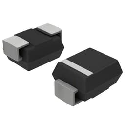
STMicroelectronics X-NUCLEO-OUT07A1
Manufacturer No:
X-NUCLEO-OUT07A1
Manufacturer:
STMicroelectronics
Package:
Description:
INDUSTRIAL DIGITAL OUTPUT EXPANS.IPS4260LM Power Distribution Switch (Load Switch) Power Management Nucleo Platform Evaluation Expansion Board
Quantity:

In Stock :8587
Looking for price or availability? Send us an RFQ and our sales team will respond quickly.
Shipping & Availability


Fast worldwide shipping via DHL, FedEx, UPS, and EMS.
Shipped from:HK Warehouse
Expected Shipping:Sun, May 31 - Mon, Jun 1, 2026
Lead Time:Inquire about availability
Date Code:Within 2 Years
Payment


We support multiple secure payment methods including PayPal, Visa, MasterCard, and American Express. All transactions are protected with advanced encryption to ensure secure and reliable payments.
Authenticity Guarantee
All components supplied by Aichiplink are sourced from trusted global suppliers and verified through strict in-house inspection and quality control procedures.
Quality Assurance
Certified in-house inspection and testing facilities ensure all components meet internationally recognized quality standards.
User Guide
Aichiplink operates certified in-house inspection and testing facilities to ensure all electronic components meet internationally recognized quality and compliance standards. Our quality management system is verified through ISO 9001 certification and industry-standard inspection procedures.
PURCHASE
Please verify all part numbers, quantities, and packaging preferences before placing your order. If substitutions are acceptable, please indicate this clearly. For time-sensitive projects, confirm estimated delivery dates and stock availability in advance. Once submitted, changes or cancellations may not be possible, especially for items marked as non-cancellable/non-returnable (NCNR). For international shipments, please ensure all import documentation is complete and accurate to avoid delays.
MEANS OF PAYMENTFor your convenience, we accept multiple payment methods in USD, including PayPal, Credit Card, and Wire Transfer. Net terms may be available for qualified customers upon approval.
RFQ (REQUEST FOR QUOTATIONS)Please ensure the part numbers and quantities are accurate and complete when submitting your RFQ.
Provide target prices and acceptable alternatives, if any, to speed up the quotation process.
Quotations are subject to stock availability and may vary with market conditions. Prices and lead times are not guaranteed until a purchase order is confirmed. Ensure your contact details are correct to avoid delays in response.
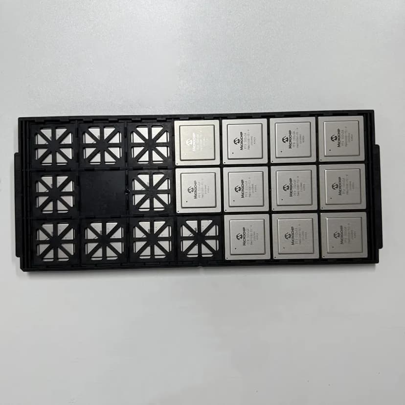
Step1:Prepare product
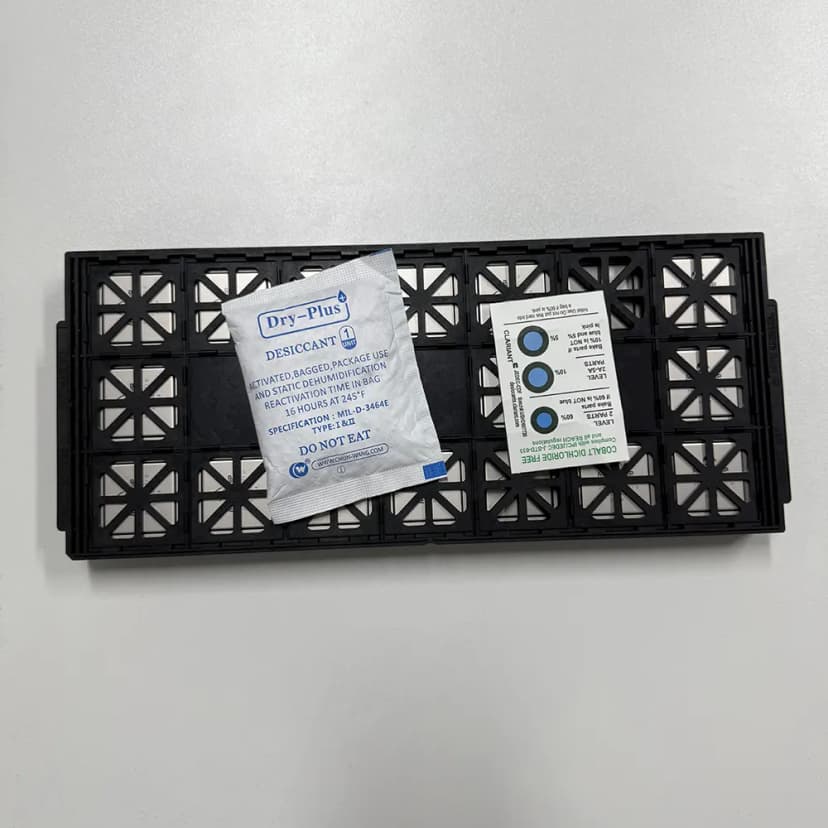
Step2:Desiccant Protection
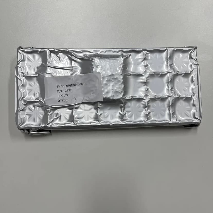
Step3:Vacuum Packaging
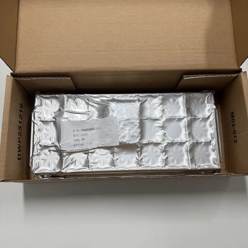
Step4:Individual Package
Step5:Anti-collision Filling
Step6:Packaging Box
SHIPPING COST
1. Shipping starts at $40, but some countries will exceed $40. For example (South Africa, Brazil, India, Pakistan, Israel, etc.).
2. Some specific products need to reach the minimum order quantity.
3. It may cost additional remote fees for delivery if you are in a remote area.
Currently, our products are shipped through DHL, FedEx, SF, and UPS.
DELIVERY TIME1. Once the goods are shipped, estimated delivery time depends on the shipping methods you chose: FedEx International, 5-7 business days.
2. For in-stock parts, orders normally could be shipped out within 1-2days.
X-NUCLEO-OUT07A1 Information
STMicroelectronics X-NUCLEO-OUT07A1 technical specifications, attributes, parameters and parts with similar specifications to STMicroelectronics X-NUCLEO-OUT07A1.
- Type
- Parameter
- Core Product
- IPS4260LM
- ECCN US
- EAR99
- ECCN EU
- NEC
- Packing Type
- Not Applicable
- RoHS Status
- Grade
- Industrial
- Package Name
- CARD
- Core Product
- IPS4260LM
- ECCN US
- EAR99
- ECCN EU
- NEC
- Type
- Parameter
- Packing Type
- Not Applicable
- RoHS Status
- Grade
- Industrial
- Package Name
- CARD
Download datasheets and manufacturer documentation for STMicroelectronics X-NUCLEO-OUT07A1.
Data sheet:

The X-NUCLEO-OUT07A1 industrial digital output expansion board for STM32 Nucleo provides a powerful and flexible environment for the evaluation of the driving and diagnostic capabilities of the IPS4260LM quad low-side smart power solid state relay, in a digital output module connected to 0.5 A industrial loads.
Dual channels and single channel configurations are possible by proper setting of J9 and J10 (see below).
The X-NUCLEO-OUT07A1 interfaces with the microcontroller on the STM32 Nucleo via STISO620 and STISO621 and Arduino®R3 connectors. The expansion board can be connected to either a NUCLEO-F401RE or a NUCLEO-G431RB development board.
The digital isolators STISO620 and STISO621 (featuring 2.8k VRMS galvanic isolation) and the isolated dc-dc DC1 (featuring 3kVDC isolation) protects the logic side from the typical harsh environment on the process side.
The logic side is the application side of the MCU and it is supplied by the VISO_L rail (3.3 or 5.0 V). When the X-NUCLEO-OUT07A1 is stacked on a NUCLEO-F401RE, or on a NUCLEO-G431RB, the VISO_L is supplied by the Nucleo board if connected to a PC/Laptop by USB cable. If the X-NUCLEO-OUT07A1 is used standalone, then VISO_L can be supplied by the CN6[4] (SW1 = close 1-2) or CN6[5] (SW1 = close 2-3).
The process side is the application side beyond the galvanic isolation barrier. On the process side there are two supply rails: the 5V_P rail (5.0 V) and one rail between the 10V_P (SW7 close 1-2) and the V_FIELD_RP rail (SW7 close 2-3).
Both the 5V_P and the 10V_P rails are generated by the DC1, while the V_FIELD_RP rail is supplied externally.
The 5V_P rail supplies both the digital isolators and the red diagnostic LEDs D7 (open load detection) and D8 (overload and overtemperature diagnostic).
The 10V_P rail supplies the IPS4260LM (U1): the loads are connected between the CN2[1, 2] and CN3[1, 2] connectors and the process side supply rail (typically 24 V). The reference rail (ground) of the power process side supply rail must be connected to CN1[2], too.
Alternatively (SW7 close 2-3) the V_FILED_RP rail supplies U1: the loads are connected between the CN2[1, 2] and CN3[1, 2] connectors and the process side supply rail (typically 24 V). The positive pole and the ground of the power process side supply rail must be connected to CN1[1] and CN1[2], respectively.
The SW8 allows the selection of which external TVS is used for the demagnetization of the inductive load and for sustaining the surge pulse on the output stage. Setting SW8 close to 1-2 the D9 is selected: this selection is valid both if U1 is supplied by the 10V_P or by the V_FIELD_RP rail. Setting SW8 close to 2-3 the D10 is selected: this selection is valid only when U1 is supplied by the V_FIELD_RP.
The four low side power switches integrated in U1 can be activated/deactivated by the control signals IN1_L, IN2_L, IN3_L and IN4_L: by default, these signals are controlled by CN5[2,1] and CN9[8,7] through SW2[1-2], SW3[1-2], SW4[1-2] (IN4_L goes through direct connection to U6). .
The four on board green LEDS D1, D2, D3, and D4 can be enabled by closing J6[1-2, 3-4, 5-6, 7-8]: these are driven ON/OFF according to the status (active/inactive) of the respective low side power switch (OUT1, OUT2, OUT3, OUT4) integrated in the U1.
The user can enable/disable the cutoff featured by U1 by J8[7-8]: open (cutoff active) or closing (cutoff disabled).
Also, J8[1-2, 3-4, 5-6] allows the user can set the desired current limitation level (J8[1-2] ==> 0.5A; J8[3-4] ==> 1A; J8[5-6] ==> 2A). The J9 and J10 allow the user to easily parallelize the input and output channels and achieve dual channel low side (J9[1-2, 5-6] and J10[1-2, 5-6]) or single channel low side (J9[1-2, 3-4, 5-6] and J10[1-2, 3-4, 5-6]).
The open load detection feature offered by U1 is enabled only when the J7[1-2, 3-4, 5-6, 7-8] are closed. Note that the signalization of D7 must be ignored when J7 is open.
The two cumulative diagnostic signals FLT_L (overload and overtemperature) and OL_L (open load) are available on the CN9[6] (SW6[1-2]) and on CN9[5], respectively.
The four per-channel overload diagnostic signals DIAG1_L, DIAG2_L, DIAG3_L, DIAG4_L are available on the CN5[10] (SW5[1-2]), CN5[9], CN8[6] and CN8[5], respectively.
It is also possible to evaluate a system composed of a X-NUCLEO-OUT07A1 stacked on other expansion boards.
- Based on the IPS4260LM quad low-side switch, which features:
- Operating range 8 to 50 V
- High Speed operation (trise, tfall < 1us)
- Process side operating current: configurable from 350 mA (per channel) up to 2 A (parallelized channels)
- Low-power dissipation (RON(TYP) = 260 mΩ)
- Configurable low dissipative cutoff function in overload conditions
- Per-channel overload, short circuit, and thermal junction protections
- Fast decay of inductive loads with integrated catch diodes
- Open load detection
- Undervoltage lock-out
- Loss of supply / loss of ground protection
- HTSSOP20 package
- Galvanic isolation between logic and process sides by STISO620, STISO621 digital isolators and isolated DC-DC converter
- Selectable supply of the IPS4260LM from on board isolated dc-dc converter (SW7 close 1-2), or from 24 V supply rail (SW7 close 2-3)
- Process side operating range: 10 V (SW7 close 1-2) or 10 to 30 V (SW7 close 2-3)
- Process side supply rail reverse polarity protections (J1 open when SW7 = close 2-3)
- Application board logic side operating voltage 3.3 (SW1 close 1-2) or 5 V (SW1 close 2-3)
- Green LEDs for outputs on/off status (J6 close 1-2, 3-4, 5-6, 7-8)
- Open load detection enable (J7 close 1-2, 3-4, 5-6, 7-8) / disable (J7 open)
- Red LEDs for overload/thermal warning (D8) and open load (D7) diagnostic
- Selectable current limitation level (J8 close 1-2 = 0.5A, or 3-4 = 1A, or 5-6 = 2A)
- Cutoff enable (J8 open 7-8) / disable (J8 close 7-8) options
- Per channel overload diagnostic available on CN5[9,10] and CN8[5, 6]
- Easy parallelization of input signals (J9) and output channels (J10)
- Compatible with STM32 Nucleo development boards
- Equipped with Arduino® UNO R3 connectors
- RoHS and China RoHS compliant
- CE certified
AIChipLink – Your Trusted Electronic Components Distributor

12.28 M
Listed Part Number
3,000+
Leading Manufacturers
4.9 M
In-stock SKU
15,000+
Warehouse Area(㎡)