Electronics enthusiasts often rely on the s8050 transistor for reliable switching and amplification. The s8050 transistor features a straightforward pin configuration, making it ideal for beginners. Accurate identification of the 8050 transistor pinout ensures correct placement of the base pin, collector pin, and emitter. The base pin plays a crucial role in controlling the transistor. Understanding the s8050 and its pin configuration helps prevent circuit errors. Many projects choose the s8050 transistor for its dependable performance. The s8050 transistor remains popular due to its simple 8050 transistor pinout and clear labeling of each base pin and collector pin.
Key Takeaways
-
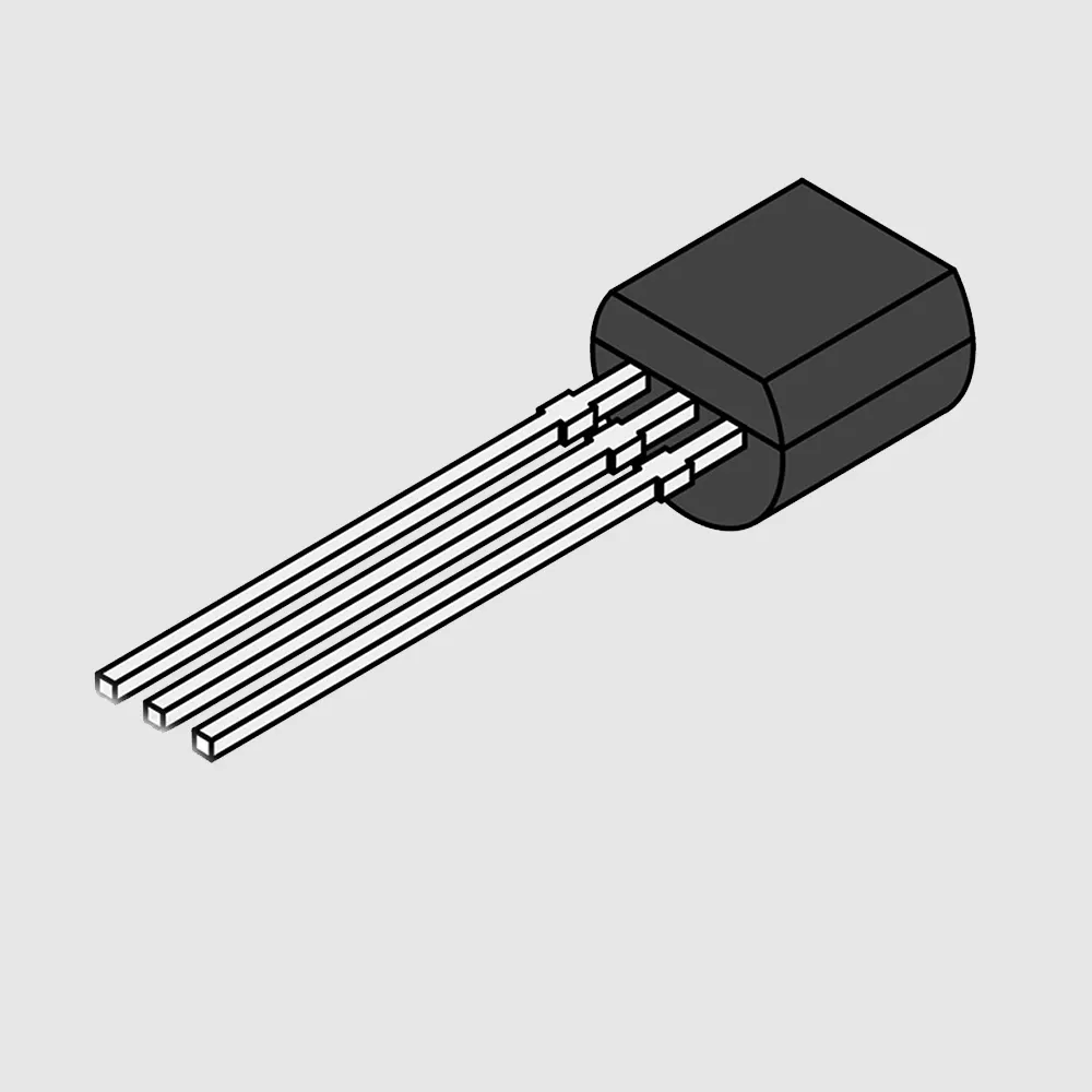
The S8050 transistor has a simple pinout: emitter on the left, base in the middle, and collector on the right when viewed from the flat side with leads down.
-
Understanding the S8050 pin configuration helps avoid wiring mistakes and ensures reliable switching and amplification in circuits.
-
The transistor supports up to 700mA collector current and 25V collector-emitter voltage, making it suitable for driving small motors, LEDs, and relays.
-
Common equivalents like 2N2222 and BC337 can replace the S8050, but always check datasheets to match voltage, current, and gain ratings.
-
The S8050 is widely used in microcontroller projects for switching loads safely and amplifying weak signals in audio and sensor circuits.
8050 Transistor Pinout
Pinout Diagram
The 8050 transistor pinout helps users connect the s8050 transistor correctly in any circuit. When looking at the s8050 transistor from the flat side with the leads pointing downward, the pinout diagram shows the following order from left to right:
   _______
  |       |
  |       |
  |_______|
   | | |
   1 2 3

  1: Emitter
  2: Base
  3: Collector
This pinout diagram makes it easy to identify each terminal. The emitter pin sits on the left, the base pin occupies the center, and the collector pin is on the right. The s8050 transistor uses this standard pin configuration to simplify installation and reduce wiring mistakes. Most datasheets and circuit diagrams use this same layout for the 8050 transistor pinout.
Physical Identification
Identifying the pins on the s8050 transistor requires careful observation. The flat side of the s8050 transistor body acts as a reference point. Hold the s8050 transistor so the flat side faces you and the leads point downward. The pin order from left to right becomes:
-
Emitter pin
-
Base pin
-
Collector pin
The emitter pin usually connects to ground or a reference voltage. The base pin sits in the middle and controls the transistor’s switching action. The collector pin connects to the load, such as a motor or LED.
The s8050 transistor pinout follows this arrangement to support reliable operation. The emitter pin manages current flow and ensures the correct direction. The base pin acts as the control terminal. A small current or voltage at the base pin allows the s8050 transistor to switch on or off. The collector pin collects current and delivers it to the output device. This pin configuration enables the s8050 transistor to work as a switch or amplifier in many circuits.
Tip: Always double-check the 8050 transistor pinout before soldering. Incorrect connections can damage the s8050 transistor or the circuit.
The s8050 transistor pinout design supports precise current control. For example, in a switching circuit, the emitter pin connects to ground, the base pin receives the control signal, and the collector pin connects to the load. This arrangement ensures the s8050 transistor operates efficiently and reliably.
The s8050 transistor remains popular because its pinout diagram and pin configuration are easy to remember. The clear labeling of the emitter pin, base pin, and collector pin helps beginners and experts avoid mistakes. Understanding the 8050 transistor pinout allows users to build circuits with confidence.
S8050 Datasheet
Key Specifications
The s8050 transistor stands out for its reliable electrical characteristics. Engineers and hobbyists often choose the s8050 for its consistent performance in switching and amplification. The s8050 transistor datasheet lists several important parameters that help users understand its capabilities. The following table summarizes the most relevant specifications for the s8050:
| Parameter | Value/Description |
|---|---|
| Maximum Collector Current (Ic) | 700 mA (Saturation Region) |
| Collector-Emitter Voltage (VCE) | 25 V |
| Collector-Base Voltage (VCB) | 40 V |
| Base Current Limit | 5 mA |
| Maximum DC Current Gain (hFE) | Up to 300 (typical around 200) |
| Power Dissipation | 1 to 2 Watts |
| Base-Emitter Saturation Voltage | 1.2 V |
| Operating Temperature Range | -55°C to 150°C |
The s8050 transistor offers a maximum collector current of 700 mA, which allows it to drive small motors, relays, or multiple LEDs. The collector-emitter voltage rating of 25 V ensures safe operation in low-voltage circuits. The current gain, or hFE, can reach up to 300, making the s8050 suitable for signal amplification. The s8050 also features a power dissipation rating between 1 and 2 watts, which helps prevent overheating during continuous use.
Note: The s8050 transistor datasheet provides these values to help users select the right component for their project.
Maximum Ratings
Understanding the maximum ratings of the s8050 is essential for safe and reliable circuit design. Exceeding these limits can damage the s8050 transistor or cause circuit failure. The table below highlights the most important maximum ratings for the s8050:
| Specification | Maximum Value | Performance Impact Description |
|---|---|---|
| Collector Current (IC) | 700 mA | Determines the largest load the s8050 can handle without damage. |
| Collector-Emitter Voltage (VCE) | 25 V | Sets the highest voltage the s8050 transistor can withstand between collector and emitter. |
| Collector-Base Voltage (VCB) | 40 V | Indicates the maximum voltage between collector and base for the s8050. |
| Power Dissipation | 2 W | Limits the total power the s8050 can safely convert to heat. |
| Base-Emitter Voltage (VBE) | 6 V | Maximum voltage allowed across the base-emitter junction of the s8050 transistor. |
| Operating Temperature Range | -55°C to 150°C | Defines the safe temperature range for the s8050 during operation. |
The s8050 transistor’s maximum collector current of 700 mA means it can control moderate loads without risk. The 25 V collector-emitter voltage rating protects the s8050 from voltage spikes. The power dissipation rating of up to 2 W ensures the s8050 can operate in circuits with higher current flow, as long as proper heat management is used. The s8050 transistor’s current gain allows it to amplify weak signals, making it a good choice for audio and sensor circuits.
The s8050 transistor’s datasheet values help users avoid exceeding safe limits. By following these ratings, designers can ensure the s8050 will perform reliably in a wide range of applications. The s8050 transistor remains a popular choice for both switching and amplification because of these dependable specifications.
S8050 Equivalent
Common Alternatives
Many electronics projects use the s8050 for switching and amplification. Sometimes, a circuit needs a replacement for the s8050 transistor due to availability or specific requirements. Several transistors can serve as direct substitutes for the s8050. Common alternatives include:
-
2N2222: This NPN transistor offers similar voltage and current ratings. It works well in switching and small signal amplification.
-
BC337: Another popular NPN transistor, the BC337 matches the s8050 in many low-power applications.
-
S9013: This transistor shares a similar pinout and electrical characteristics with the s8050.
-
PN2222A: Widely used in hobby circuits, this transistor can replace the s8050 in most cases.
These alternatives allow users to maintain circuit performance when the s8050 is not available. Each substitute provides reliable operation in small-signal and switching circuits.
Selection Tips
Choosing the right replacement for the s8050 transistor requires careful attention to several factors. The following table summarizes important criteria and practical advice for selecting an alternative:
| Criterion | Explanation | Supporting Detail |
|---|---|---|
| Unsuitability for high current loads | The s8050 overheats quickly when driving motors above 300mA. | Users report rapid heating and damage at higher currents. |
| Importance of current limiting | Current limiting protects the s8050 and similar transistors from failure. | Practical advice highlights the need for current-limiting resistors. |
| Use of power transistors | Power transistors like TIP31C handle higher loads safely. | TIP31C requires more base current but supports larger currents. |
| Consideration of gain (Beta) | Gain affects the base current needed for switching. | Datasheets provide Beta values for calculation. |
| Use of power MOSFETs | Power MOSFETs offer efficient switching for motors. | Application notes recommend FETs for better efficiency. |
| Protective components | A reversed diode across inductive loads prevents voltage spikes. | Standard practice in motor driver circuits. |
| Consulting datasheets | Datasheets give essential parameters for safe operation. | Always check datasheet values before substitution. |
Tip: Always check the datasheet for the s8050 and any alternative. Matching voltage, current, and gain ensures safe and reliable operation.
Selecting the right substitute for the s8050 depends on the application. For higher current needs, power transistors or MOSFETs work better. For small-signal circuits, direct replacements like the 2N2222 or BC337 provide similar performance. Proper current limiting and protective components help prevent damage to the s8050 transistor and its alternatives.
S8050 Transistor Uses

Applications
The s8050 serves as a versatile component in many electronic projects. Designers often use this device for switching and amplification tasks. In microcontroller-based systems, the s8050 acts as a bridge between low-power control signals and higher-power loads. For example, a microcontroller can send a small current to the base of the s8050, which then allows a larger current to flow through an LED or other device. This switching action protects the microcontroller from excessive current.
The s8050 also finds use in relay driver circuits. When a control signal reaches the base, the s8050 conducts and energizes the relay coil. This action enables the circuit to control devices that require more current or voltage than the microcontroller can provide directly. The s8050’s ability to handle moderate currents makes it suitable for driving small motors, buzzers, and indicator lamps.
Note: The s8050 helps isolate sensitive control electronics from higher-power loads, improving safety and reliability.
Example Circuits
Many practical circuits rely on the s8050 for dependable operation. The following examples show how engineers and hobbyists use this component:
-
Microcontroller-Driven LED Switch
A GPIO pin from a microcontroller connects to the base of the s8050 through a resistor. When the pin goes high, the s8050 switches on and lights an LED connected to the collector. This setup allows the microcontroller to control the LED without risk of overload. -
Relay Driver Circuit
In a relay driver, the s8050 receives a signal from an optocoupler or microcontroller. The transistor then completes the circuit for the relay coil, which may draw around 70mA. Additional parts, such as a capacitor across the coil and an LED indicator, can improve performance and safety. -
Audio Amplifier Stage
The s8050 can amplify weak audio signals in small speaker circuits. Placing the s8050 in the preamplifier stage boosts the signal before it reaches the main amplifier.
| Circuit Type | S8050 Role | Benefit |
|---|---|---|
| LED Switch | Switch | Protects microcontroller |
| Relay Driver | Switch | Handles higher load current |
| Audio Amplifier | Amplifier | Boosts weak signals |
The s8050’s simple design and reliable performance make it a favorite for both learning and real-world applications.
Readers can now identify the 8050 transistor pinout, understand key datasheet specifications, and select suitable equivalents for their projects. The diagrams and tables in this guide offer quick reference for building reliable circuits. For deeper learning, they should explore more example circuits or review the official datasheet.
Using the right transistor helps ensure safe and efficient electronic designs.
FAQ
What is the main function of the S8050 transistor?
The S8050 transistor works as a switch or amplifier in electronic circuits. It controls current flow using a small signal at the base pin. Many hobbyists use it for simple switching tasks.
Can the S8050 replace a 2N2222 transistor?
Yes, the S8050 can replace a 2N2222 in most low-power circuits. Both have similar pinouts and electrical ratings. Always check the datasheet to confirm compatibility.
How do you test if an S8050 transistor is working?
Use a digital multimeter in diode mode. Measure between base-emitter and base-collector. A good transistor shows a voltage drop (about 0.6V) in one direction and none in the other.
What happens if you connect the pins incorrectly?
Incorrect pin connections can damage the S8050 transistor or the circuit. The device may overheat, fail to switch, or cause other parts to malfunction.
Always double-check the pinout before soldering.
Is the S8050 suitable for audio amplification?
Yes, the S8050 works well in small audio amplifier circuits. It can boost weak signals for headphones or small speakers.
For higher power audio, use a dedicated audio transistor.
Written by Jack from AIChipLink.
AIChipLink, one of the fastest-growing global independent electronic components distributors in the world, offers millions of products from thousands of manufacturers, and many of our in-stock parts is available to ship same day.
We mainly source and distribute integrated circuit (IC) products of brands such as Broadcom, Microchip, Texas Instruments, Infineon, NXP, Analog Devices, Qualcomm, Intel, etc., which are widely used in communication & network, telecom, industrial control, new energy and automotive electronics.
Empowered by AI, Linked to the Future. Get started on AIChipLink.com and submit your RFQ online today!


