Introduction
What is resistor definition?A resistor is an electrical component that limits or regulates the flow of electrical current in an electronic circuit. Resistors can also be used to provide a specific voltage for an active device such as a transistor. They are designed to have a specific resistance value, measured in ohms .
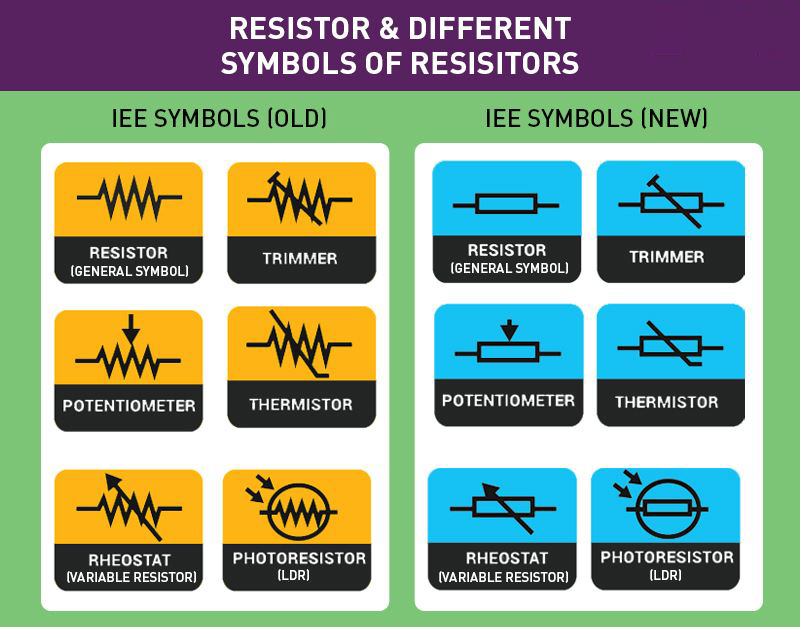
The resistor symbol as a kind of identification is unique to each type of resistor. There are many types of resistors , which can be divided into fixed resistors , variable resistors, special resistors, high-power resistors, low-power resistors, etc. They basically have different symbols for representation. This article mainly explains the symbol of some common resistors , including text symbols and graphical ones in different standards.
Before this, we should konw that, in electronics, understanding the concepts of the tolerance of a resistor and the resistor color code is vital. Tolerance refers to the permissible deviation in the resistance value that a resistor may have from its stated value. It's usually expressed as a percentage. This variation is crucial as it affects the overall performance of the circuit in which the resistor is used.
On the other hand, the resistor color code is a reliable and efficient method to indicate the resistance value and its tolerance. Each color corresponds to a specific number, which when read in order, provides the value of the resistor and its tolerance. For instance, a resistor with color bands of brown, black, red, and gold signifies a resistance value of 1,000 ohms (or 1 kilohm) with a tolerance of 5%. Therefore, by appropriately interpreting the color code, one can determine the precise specifications of a resistor, ensuring the efficient functioning of the electronic circuit.
Overview of Resistor Types and Symbols
1.1 Types of Resistors
Resistors can be divided into general-purpose types resistors and special resistors based on their operating characteristics and their role in the circuit. General resistors are divided into fixed resistors and variable resistors.
Resistors with fixed resistance are called fixed resistors, mainly including carbon film resistors , metal film resistors , oxide film resistors, cement resistors and wire-wound resistors.
The rated power of the carbon film resistor is relatively small, generally 1/8 W to 2 W, and it is suitable for working at temperatures below 70 ℃.
Metal film resistors have high-temperature resistance and can work for a long time below 125 ℃. The resistor has a small temperature coefficient, good stability, high precision, low noise, and the power is generally 1/8 W to 3 W.
The oxide film resistor has a good heat resistance and pressure resistance and can replace the metal film resistor . Cement resistors and wire-wound resistors have large power and large volume.
There are some differences between resistance and resistor. Resistance is a property or characteristic of an object that opposes or restricts the flow of electrical current through it. It's a measure of the degree to which an object impedes the flow of electric current. The unit of resistance is the ohm (Ω). A resistor, on the other hand, is a specific electronic component that is used in electrical circuits to limit the flow of electrical current. A resistor whose resistance is continuously adjustable within a certain range is called a variable resistor or potentiometer. The prescribed resistor has two terminals and the potentiometer has three terminals.
1.2 The Unit of The Resistance and Its Symbol
The basic unit of resistance is ohm (Ω). In order to facilitate the writing of larger values of resistance, this unit is often abbreviated like current and voltage. The units of resistance from large to small are: MΩ (megaohm), kΩ (kiloohm), Ω (ohm), mΩ (milliohm), μΩ (microohm), the smaller units like “milliohm, micro "Europe" is not common. The conversion relationship between them is:
1 megohm = 1000 kohm
1 thousand ohms = 1000 ohms
1 ohm = 1000 milliohms
1 milliohm = 1000 microohm
Tip: When calculating the value in the actual work of an electrician, K usually means 1000 (especially when it is commonly used in component labeling).
1.3 Resistor Symbols and Marking Symbols
In general, resistors are usually represented by symbols such as R, RN, RF, and FS. In the circuit, the symbol of the fixed resistor and trimming resistor is R, and the symbol of the potentiometer is RP.
In order to distinguish between different types of resistance , several Latin letters are commonly used to indicate the resistor type, as shown in the figure below. The first letter R represents the resistor, the second letter represents the conductor material, and the third letter represents the shape and performance.
1.4 Resistor Types and Identification Symbols Table
| Order | Types | Name | Symbol |
| The First Letter | Main title |
Resistor Potentiometer | R W |
| The Second Letter | Conductor material |
Carbon film Metal film Metal oxide film Wire wound | T J Y X |
| The Third Letter | Shape, performance, etc. |
size Precision measuring High power | X J L G |
1.5 Technical Characteristics of Commonly Used Resistors
| Resistor Types | Rated Power(W) | Nominal Resistance Range (Ω) | Temperature Coefficient (1/℃) | Noise Potential (uV/V) | Operating Frequency |
|
RT Type Carbon Film resistors | 0.05 0.125 0.25 0.5 1.2 | 10~100×103 5.1~510×103 5.1~910×103 5.1~2×10⁶ 5.1~5.1×10⁶ | -(6~20)×10-4 | 1~5 | Below 10 MHz |
|
RU Type Silicon Carbon Film Resistor | 0.125、0.25 0.5 1.2 | 5.1~510×103 10~1×10⁶ 10~10×106 | ±(7~12)×10-4 | 1~5 | Below 10 MHz |
|
RJ Type Metal Film Resistor | 0.125 0.25 0.5 1.2 | 30~510×103 30~1×10⁶ 30~5.1×10⁶ 30~10×106 | ±(6~10)×10-4 | 1~4 | Below 10 MHz |
|
RXYC Type Wire Wound Resistor | 2.5~100 | 5.1~56×106 | - | - | Low Frequency |
|
WTH Type Carbon Film Potentiometer | 0.5~2 | 470~4.7×10⁶ | 5~10 | 5~10 | Below a few hundred KHz |
|
WX Type Wire-wound Potentiometer | 1~3 | 10~20×103 | - | - |
Low Frequency |
Symbols of Three Main Types of Resistors
2.1 Fixed Resistor
Fixed resistors are resistors whose resistance values are not adjustable or changeable. Here are some types of fixed resistors : Carbon Composition Resistor, Film or Cermet Resistor, Wirewound Resistor, Thin and Thick Film Resistor, Metal Foil Resistor
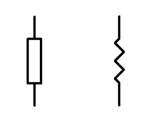
The symbol of the fixed resistor in the circuit diagram represents the resistor body with a long square, and the short lines on both sides respectively indicate the two lead-out lines of the resistor. Whether it is a carbon resistor or a metal film resistor, all resistors with a fixed resistance are represented by this symbol.
It should be noted that the graphic symbols of fixed resistors commonly used in some countries are different from the internationally recommended symbols. As shown in the figure below, the right side is the symbol of the fixed resistor of an international standard:
2.2 Variable Resistor
A variable resistor is a type of resistor whose electrical resistance value can be adjusted. There are several types of variable resistors , including: Potentiometer, Rheostat, Trimpot, Digital Potentiometer, Varistor, Thermistor and Photoresistor (or Light Dependent Resistor - LDR)
The symbol of the variable resistor in the circuit diagram still uses a long square to represent the resistor body, and an arrow to visually represent the movable sliding contact. Because the variable resistor is a variable resistance component with only two terminals, it is only represented by a lead wire and a broken line with an arrow, or by a fixed resistor symbol with an arrow.
The Standard of Resistor Symbol
There are different standards for resistor symbols , and different countries may use different resistor symbols . Some common standards are as follows:
(1)IEC 60617 (also known as British Standard BS 3939).
(2)There is also IEC 61131-3 - for ladder-logic symbols.
(3)JIC (Joint Industrial Council) symbols as approved and adopted by the NMTBA (National Machine Tool Builders Association). They have been extracted from the Appendix of the NMTBA Specification EGPl-1967
(4)ANSI Y32.2-1975 (also known as IEEE Std 315-1975 or CSA Z99-1975)
(5)IEEE Std 91/91a: graphic symbols for logic functions (used in digital electronics). It is referenced in ANSI Y32.2/IEEE Std 315.
(6)Australian Standard AS 1102. (Based on a slightly modified version of IEC 60617, Withdrawn without replacement with a recommendation to use IEC 60617)
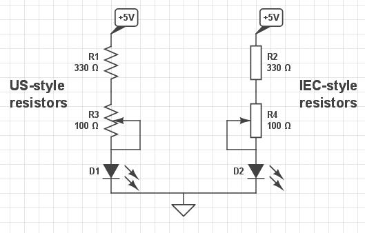
For example, many Americans are used to seeing "squiggle" -styled line segments. However, in many other countries, the normal resistor symbol is just a simple outlined rectangle (the IEC-standard symbol choice). And the IEC 60617 standard is the international standard.
FAQs About Resistor Symbols
Q:What does the resistor symbol look like in a circuit diagram?
In a circuit diagram, a resistor is often represented as a rectangle or a collection of jagged lines that obstruct the flow of electric current. American circuit diagrams tend to employ the zigzag version more frequently than the rectangular form, which is more prevalent in European schematics.
Q:Do various resistor types have distinct symbols?
Indeed, there are differences in the symbols used to represent various resistor kinds. An arrow over the typical resistor symbol, for example, indicates a variable resistor. Additional markings or variants in the symbol may be present on precision resistors or other special types to show their unique properties.
Q:In a schematic, how can I deduce the resistance value from a resistor symbol?
Usually, the resistor symbol does not include the resistance value; instead, it is placed adjacent to it. The value can be shown next to the symbol in either ohms (Ω), kilohms (kΩ), or megohms (MΩ). Color labeling is occasionally applied to real resistors but not to schematic representations.
Q:What does the resistor symbol's line representation mean?
Each 'zig' and 'zag' in the zigzag sign stands for the resistor material, which prevents electrical current from flowing, graphically showing the purpose of resistance. The schematic representation of this electronic component is made simpler by the design.
Q:Are the resistor symbols in AC and DC circuits different?
Generally, whether an AC or DC circuit is used, the resistor symbols stay the same. The resistor symbol is independent of the circuit type (DC or AC).
Q:What effects do environment and temperature have on resistors?
Temperature variations can cause some resistors to change resistance values. Temperature and humidity are two examples of environmental variables that might impact performance, especially in delicate applications.
Written by Icey Ye from AIChipLink.
AIChipLink, one of the fastest-growing global independent electronic component distributors in the world, offers millions of products from thousands of manufacturers. Whether you need assistance finding the right part or electronic components manufacturers for your design, you can contact us via phone, chat or e-mail. Our support team will answer your inquiries within 24 hours.