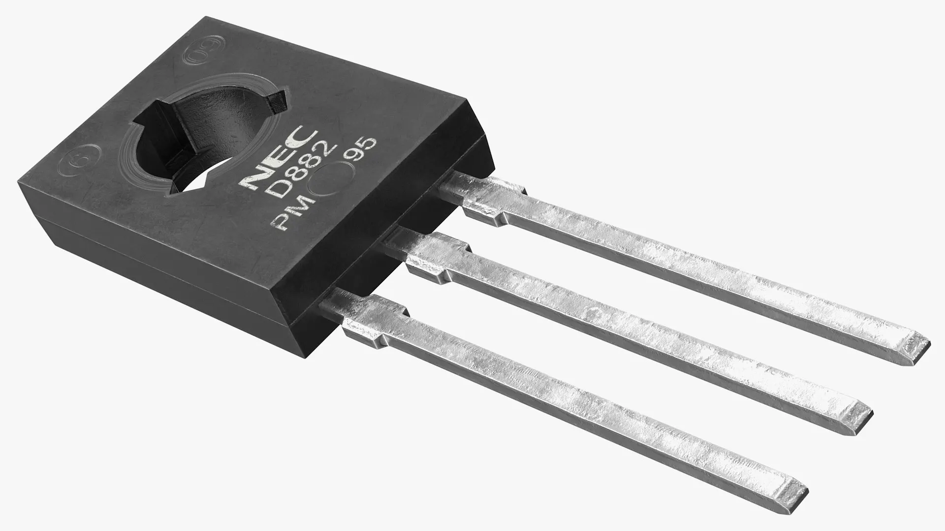
When someone examines the D882 transistor from the flat side with the leads pointing downward, the d882 transistor pinout appears as follows: pin 1 is the base, pin 2 is the collector, and pin 3 is the emitter. Accurate identification of the d882 transistor pinout ensures that the d882 operates correctly in any circuit. Incorrect placement of the transistor can cause circuit failure or permanent damage to the d882. Many beginners find that understanding the d882 transistor pinout helps prevent common mistakes while working with this transistor.
Key Takeaways
-
The D882 transistor has three pins: base, collector, and emitter, arranged left to right when holding the flat side with leads down.
-
Use a multimeter in diode mode to test the D882 transistor and confirm correct pin connections before use.
-
The D882 supports up to 3A collector current and 40V voltage, making it suitable for switching motors, relays, and amplifiers.
-
Substitutes like 2SD882 and MJE340 closely match the D882’s performance and pinout for easy replacement.
-
Always follow datasheet guidelines and use a base resistor to protect the transistor and ensure safe, reliable operation.
D882 Overview
Features
The d882 is a popular npn bipolar junction transistor designed for both switching and amplification tasks. This device offers a robust set of features that make it suitable for a wide range of electronic projects. The following table summarizes the key technical specifications:
| Specification Category | Parameter / Value |
|---|---|
| Transistor Type | NPN |
| Collector-Emitter Voltage | 30 V |
| Collector-Base Voltage | 40 V |
| Emitter-Base Voltage | 5 V |
| Collector Current | 3 A (peak 6 A for <5ms pulses) |
| Power Dissipation | 10 W to 12.5 W |
| Current Gain (hFE) | 60 to 400 (min 100 typical) |
| Transition Frequency | 100 MHz |
| Package Type | SOT-32, TO-126, SOT-89 |
| Storage Temperature Range | -55 to 150 °C |
| Environmental Compliance | Pb-Free, RoHS, Halogen free |
Key features of the d882 transistor include:
-
NPN type for general-purpose use
-
Maximum collector current of 3A, suitable for driving motors, relays, and LEDs
-
Power dissipation up to 12.5W, ideal for output stages in amplifiers
-
Wide current gain range (hFE) from 60 to 400
-
High transition frequency of 100 MHz for fast switching
-
Available in multiple package types for flexible mounting
-
Environmentally friendly options with RoHS and Halogen-free compliance
Benefits
The d882 transistor provides several advantages for circuit designers and hobbyists. Its high collector current rating allows it to control larger loads, such as motors and relays, without overheating. The wide current gain range ensures stable operation in both switching and amplification roles. Users can rely on the d882 for consistent performance in voltage regulation, relay driving, and audio power amplification.
Tip: The d882 works well as a switch when the emitter is grounded and the collector connects to the load. Adding a base resistor helps limit the base current and protects the transistor.
The d882 npn bipolar junction transistor also supports use in H-bridge circuits, DC-DC converters, and battery charging systems. Its robust construction and environmental compliance make it a safe choice for modern electronic designs. The device’s versatility and reliability have made it a standard component in many educational and professional projects.
D882 Transistor Pinout
Pin Configuration
The d882 transistor pinout follows a standard arrangement that simplifies installation and troubleshooting. When someone holds the d882 with the flat side facing them and the leads pointing downward, the pins appear from left to right as base, collector, and emitter. This pin configuration remains consistent across most manufacturers, making it easy to reference in any project. The d882 transistor pinout allows users to quickly identify each terminal and connect the transistor correctly in a circuit.
A typical pinout diagram for the d882 shows:
| Pin Number | Name | Function |
|---|---|---|
| 1 | Base | Controls current |
| 2 | Collector | Load connection |
| 3 | Emitter | Ground/return |
This pinout configuration ensures that the d882 can be used in a wide variety of circuits without confusion. The clear labeling of each pin helps prevent wiring errors and supports reliable operation.
Note: Always double-check the d882 transistor pinout before soldering or inserting the device into a breadboard. Mistakes in pin identification can lead to malfunction or permanent damage.
Pin Identification
Correctly identifying the pins of the d882 is essential for safe and effective circuit design. The base pin acts as the control terminal, the collector connects to the load, and the emitter usually connects to ground. The d882 transistor pinout remains the same regardless of the brand, which simplifies replacement and troubleshooting.
To identify the pins:
-
Hold the d882 so the flat side faces you.
-
Point the leads downward.
-
From left to right, the pins are base, collector, and emitter.
This method works for both the SOT-32 and TO-126 packages, which are common for the d882. The npn bipolar junction transistor structure of the d882 means that the base must receive a small current to allow a larger current to flow from collector to emitter.
Testing Pinout
A multimeter in diode mode provides a reliable way to confirm the d882 transistor pinout. This method checks the internal junctions and verifies correct pin identification. The following steps outline the process:
-
Set the multimeter to diode test mode.
-
Identify the suspected pins based on the pinout configuration.
-
Place the positive probe on the base and the negative probe on the collector. The display should show a forward voltage drop between 0.6V and 0.7V.
-
Place the positive probe on the base and the negative probe on the emitter. Expect a similar forward voltage drop.
-
Place the positive probe on the collector and the negative probe on the emitter. The meter should show no conduction (infinite resistance).
-
Reverse the probes on the base-collector and base-emitter pairs. The meter should now show very high or infinite resistance.
-
Optionally, measure resistance between all pins. The collector-emitter pair should show high resistance, while the base to collector and base to emitter pairs should show lower resistance.
These steps confirm the d882 transistor pinout and ensure the device is functioning as expected. This testing method applies to any npn bipolar junction transistor, including the d882, and helps prevent errors during installation.
Tip: The d882 transistor pinout does not change between different manufacturers. Users can confidently use the same pinout configuration for all d882 devices.
D882 Transistor Datasheet
Specifications
The d882 transistor datasheet provides a clear overview of the most important electrical characteristics. These values help users understand the performance and limitations of the d882 in real-world circuits. The following table summarizes the main d882 transistor specifications:
| Parameter | Typical Value / Range | Unit | Description |
|---|---|---|---|
| Collector-Emitter Voltage (Vce) | 30 | V | Maximum voltage between collector and emitter |
| Collector-Base Voltage (Vcb) | 40–60 | V | Maximum voltage between collector and base |
| Emitter-Base Voltage (Vbe) | 5–7 | V | Maximum voltage between emitter and base |
| Collector Current (Ic) | 2–3 | A | Maximum continuous collector current |
| Peak Collector Current | 5 | A | Maximum pulse current through collector |
| Base Current (Ib) | Few mA–1 | A | Maximum base current |
| Power Dissipation (Pd) | 1–10 | W | Maximum power the transistor can dissipate |
| DC Current Gain (hFE) | 35–400 | Amplification factor | |
| Transition Frequency (fT) | 3–100 | MHz | Frequency where gain drops to unity |
| Operating Junction Temp. | 150 | °C | Maximum junction temperature |
These d882 transistor specifications allow engineers and hobbyists to select the right component for their application.
Maximum Ratings
The d882 transistor datasheet lists several maximum ratings that must not be exceeded to ensure safe operation. Exceeding these values can damage the transistor or cause failure. Key maximum ratings include:
-
Maximum Collector Current (Ic): 3 Amperes (A)
-
Maximum Collector-Emitter Voltage (Vce): 40 Volts (V)
-
Maximum Collector-Base Voltage (Vcb): 60 Volts (V)
-
Maximum Emitter-Base Voltage (Vbe): 5 Volts (V)
-
Power Dissipation (Pd): 1.25–10 Watts (W)
-
Operating Junction Temperature: 150°C
Note: Always check the d882 transistor datasheet for the exact values, as they may vary slightly between manufacturers.
Datasheet Access
Accessing the official d882 transistor datasheet is simple and ensures accurate information for any project. Users can follow these steps:
-
Visit the official STMicroelectronics product page or a trusted datasheet repository such as alldatasheet.com.
-
Locate the download link for the d882 transistor datasheet, usually found near the product description.
-
Download the PDF file to review detailed d882 transistor specifications, pin configuration, and application guidelines.
-
Review additional resources on the page, such as CAD models and technical documentation, for further support.
The d882 transistor datasheet provides comprehensive technical data, helping users verify the identity and suitability of the transistor for their needs.
D882 Equivalents
Equivalent List
Many electronic projects require a substitute when the d882 is unavailable. Several transistors offer similar electrical characteristics and can serve as direct replacements. The most common equivalents include:
-
2SD882
-
MJE340
-
BC327 (PNP, for complementary circuits)
The following table compares the d882 with these alternatives. It highlights key parameters such as maximum collector current, voltage ratings, current gain, and polarity. This comparison helps users select a suitable substitute based on their circuit requirements.
| Parameter | D882 | 2SD882 | MJE340 | C945 | BC327 (PNP) |
|---|---|---|---|---|---|
| Maximum Collector Current | 3 A | Similar | Comparable | Lower | Comparable |
| Collector-Emitter Voltage | 40 V | Similar | Comparable | Lower | Comparable |
| DC Current Gain (hFE) | 35 to 240 | Similar range | Comparable | Slightly lower | Comparable |
| Power Dissipation | 1.25 W | Similar | Comparable | Lower | Comparable |
| Transition Frequency (fT) | ~3 MHz | Similar | Comparable | Lower | Comparable |
| Polarity | NPN | NPN | NPN | NPN | PNP (inverted) |
Note: The 2SD882 and MJE340 closely match the d882 in both electrical ratings and pinout, making them reliable substitutes. The C945 works best for low-power applications. The BC327, as a PNP transistor, is not a direct replacement but can be used in complementary designs.
Substitute Selection
Selecting the right substitute for the d882 depends on the specific needs of the circuit. The 2SD882 and MJE340 provide nearly identical performance, so they fit most applications where the d882 is used. Their maximum collector current and voltage ratings align well with the original device. The C945 offers a solution for circuits with lower current demands, such as signal amplification or small switching tasks.
Engineers should always check the polarity before choosing a replacement. The BC327, for example, has a PNP structure, which means it operates with opposite current flow compared to the d882. This transistor works in complementary or push-pull circuits but does not serve as a direct drop-in replacement.
Careful review of datasheets ensures that the substitute matches the required ratings for current, voltage, and gain. Matching these parameters helps maintain circuit stability and prevents component failure. When in doubt, users should select a substitute with equal or higher ratings than the original d882.
D882 Applications
Common Uses
The d882 transistor appears in many electronic circuits because of its versatility and reliability. Engineers often select this device for switching and amplification tasks. The d882 works well in audio amplifier output stages, relay drivers, and small motor controllers. Many power supply circuits use the d882 to regulate voltage or drive loads. Students and hobbyists often choose this component for school projects and DIY electronics.
A table below shows some typical d882 transistor applications:
| Application Area | Example Use Case |
|---|---|
| Audio Amplifiers | Output stage, preamp circuits |
| Power Supplies | Voltage regulation, switching |
| Motor Control | Small DC motor drivers |
| Relay Driving | Switching relays in automation |
| LED Lighting | High-power LED switching |
Note: The d882 can handle moderate power loads, making it suitable for both analog and digital projects.
Safe Usage
Proper handling of the d882 ensures long-term performance. Users should always check the datasheet before connecting the transistor to a circuit. Exceeding the maximum voltage or current ratings may damage the device. Adding a base resistor helps control the base current and prevents overheating. Good ventilation or a heat sink can improve heat dissipation during high-power operation.
-
Always match the pinout to the circuit diagram.
-
Avoid reverse polarity connections.
-
Use a suitable base resistor to limit current.
-
Monitor temperature during extended use.
Tip: Safe usage of the d882 extends the life of the transistor and protects other components in the circuit.
Testing
Testing the d882 before installation helps prevent circuit failure. A digital multimeter in diode mode can check the base-collector and base-emitter junctions. The user should see a voltage drop of about 0.6V to 0.7V in one direction and high resistance in the other. If the readings do not match, the transistor may be faulty.
Steps for testing:
-
Identify the pins using the standard pinout.
-
Set the multimeter to diode mode.
-
Measure between base and collector, then base and emitter.
-
Confirm expected voltage drops.
Regular testing ensures reliable d882 transistor applications in any project.
Understanding the correct transistor pinout helps prevent mistakes and ensures safe operation in any project. Checking the datasheet gives users accurate information about ratings and specifications. When a replacement is needed, reviewing equivalent transistor options supports reliable circuit performance. Readers can apply these tips in real-world projects.
Always consult the datasheet before using a new transistor to avoid errors and protect components.
FAQ
What is the maximum current the D882 transistor can handle?
The D882 transistor supports a maximum collector current of 3 amperes. For short pulses, it can handle up to 6 amperes. Exceeding these values may damage the device.
Can the D882 replace a 2N2222 transistor?
The D882 can replace a 2N2222 in some circuits, but only if the voltage and current ratings match. Always check both datasheets before substitution.
How does someone test if a D882 transistor is working?
A user can test the D882 with a digital multimeter in diode mode. Measure the base-collector and base-emitter junctions. A good transistor shows a voltage drop of about 0.6V to 0.7V.
Is the D882 suitable for audio amplifier circuits?
Yes, the D882 works well in audio amplifier output stages. Its high current gain and power dissipation make it a good choice for small to medium audio projects.
Written by Jack from AIChipLink.
AIChipLink, one of the fastest-growing global independent electronic components distributors in the world, offers millions of products from thousands of manufacturers, and many of our in-stock parts is available to ship same day.
We mainly source and distribute integrated circuit (IC) products of brands such as Broadcom, Microchip, Texas Instruments, Infineon, NXP, Analog Devices, Qualcomm, Intel, etc., which are widely used in communication & network, telecom, industrial control, new energy and automotive electronics.
Empowered by AI, Linked to the Future. Get started on AIChipLink.com and submit your RFQ online today!


