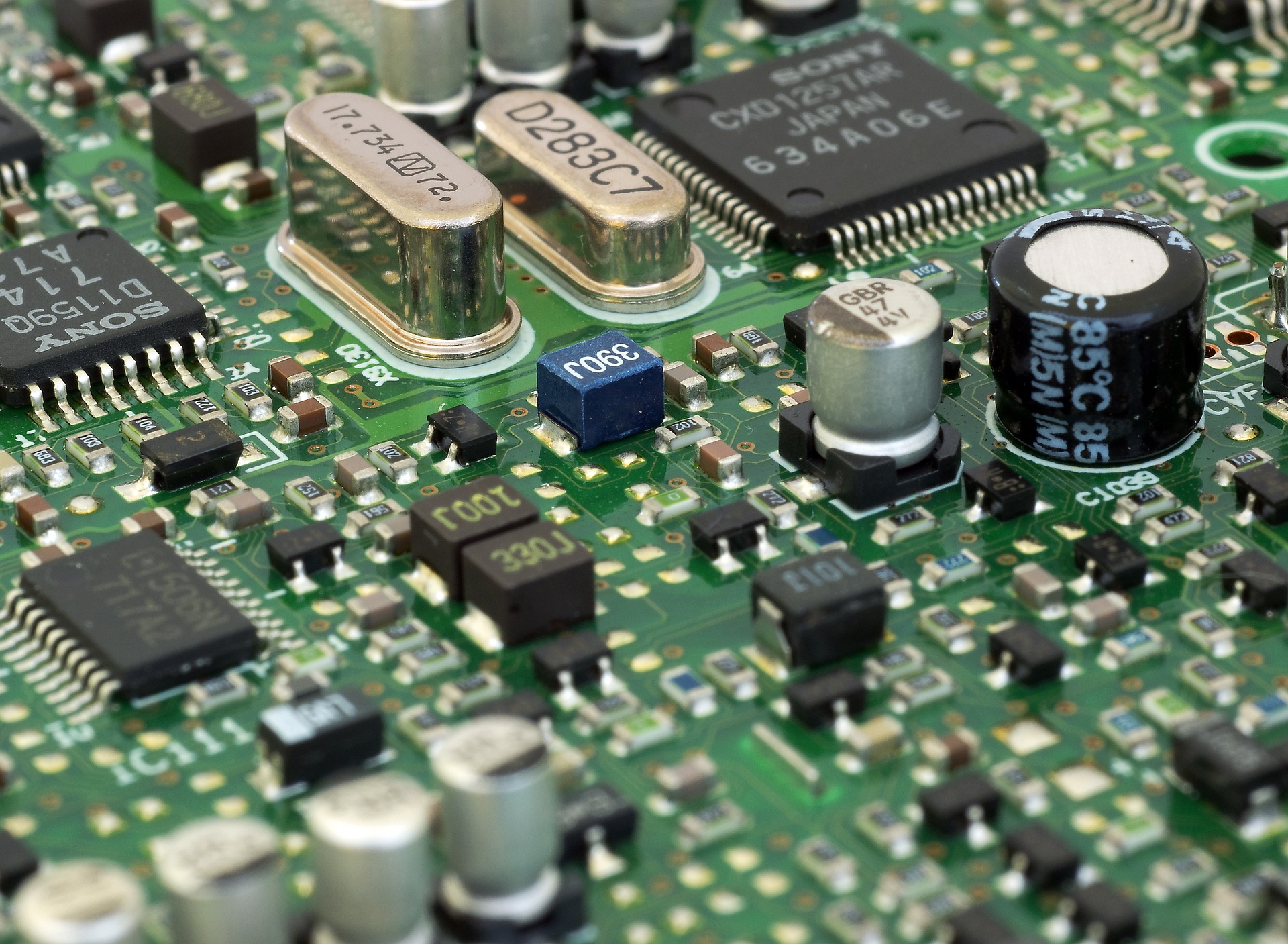
The 74HC595N shift register is an essential integrated circuit (IC) in digital electronics, widely used for expanding the number of outputs available from microcontrollers and other digital devices. This article delves into the functionality, pinout, circuit diagrams, and practical applications of the 74HC595N, along with references to its datasheet for further technical details.
What is a 74HC595N Shift Register?
The 74HC595N is an 8-bit serial-in, parallel-out shift register. It belongs to the 74HC family of ICs, known for their high-speed performance and low-power consumption. The primary function of this shift register is to convert serial data input into parallel data output, allowing for the control of multiple output devices, such as LEDs, from a single microcontroller pin.
The 74HC595N facilitates easier communication between digital components, providing a means to manage multiple outputs without overwhelming the limited pin availability of microcontrollers. This makes it an invaluable tool for hobbyists and professionals working on electronic projects.
Features of the 74HC595N
Some notable features of the 74HC595N include:
• 8-bit shift register: Capable of storing and shifting 8 bits of data.
• Parallel output: Outputs can be accessed simultaneously.
• Data transmission: Data can be shifted in on the rising edge of the clock signal.
• Serial output: Allows cascading multiple 74HC595Ns for controlling even more outputs.
• Low power consumption: Suitable for battery-powered applications.
• Wide operating voltage: Typically operates between 2V to 6V.
74HC595N Pinout
Understanding the pinout of the 74HC595N is crucial for its proper implementation in circuit designs. The IC comes in a standard 16-pin dual-in-line package (DIP). Here is a detailed breakdown of the 74HC595N pinout:
• Pin 1 (QA): Output pin 0 (first bit).
• Pin 2 (QB): Output pin 1 (second bit).
• Pin 3 (QC): Output pin 2 (third bit).
• Pin 4 (QD): Output pin 3 (fourth bit).
• Pin 5 (QE): Output pin 4 (fifth bit).
• Pin 6 (QF): Output pin 5 (sixth bit).
• Pin 7 (QG): Output pin 6 (seventh bit).
• Pin 8 (QH): Output pin 7 (eighth bit).
• Pin 9 (GND): Ground pin.
• Pin 10 (DS): Serial data input pin.
• Pin 11 (STROBE): Latch pin for output.
• Pin 12 (SHCP): Shift clock input pin.
• Pin 13 (DS): Serial data input pin.
• Pin 14 (MR): Master reset pin (active low).
• Pin 15 (OE): Output enable pin (active low).
• Pin 16 (VCC): Supply voltage pin.
Each pin serves a specific purpose, and a thorough understanding of their functions is essential for effectively using the 74HC595N in circuit designs.
74HC595N Circuit Diagram
When incorporating the 74HC595N into a project, a well-structured circuit diagram is critical. Below is a simple example circuit that demonstrates how to connect the 74HC595N to a microcontroller, such as an Arduino.
Components Required
• 74HC595N shift register
• Arduino board
• 8 LEDs
• 220-ohm resistors (for LEDs)
• Breadboard and jumper wires
Circuit Connections
1. Connect the Ground (GND): Connect pin 9 of the 74HC595N to the ground of the Arduino.
2. Power Supply (VCC): Connect pin 16 of the 74HC595N to the 5V output of the Arduino.
3. Serial Data Input (DS): Connect pin 11 of the 74HC595N to a digital pin on the Arduino (e.g., pin 2).
4. Shift Clock (SHCP): Connect pin 12 of the 74HC595N to another digital pin on the Arduino (e.g., pin 3).
5. Latch Pin (STROBE): Connect pin 11 to a third digital pin on the Arduino (e.g., pin 4).
6. Connect Outputs to LEDs: Connect pins 1 through 8 of the 74HC595N to the anodes of the LEDs. Connect the cathodes to ground via a 220-ohm resistor.
This circuit allows the Arduino to control the LEDs through the 74HC595N, shifting data in and out to manage the state of each LED.
Using the 74HC595N in Projects
The 74HC595N can be utilized in a variety of applications, including:
1. LED Control: By expanding the number of LEDs that can be controlled using limited pins on a microcontroller.
2. Seven-Segment Displays: Driving multi-digit displays using fewer pins.
3. Relays and Motors: Controlling devices requiring higher current using transistor switches connected to the outputs.
4. Data Communication: Cascading multiple 74HC595Ns for even greater output control.
The versatility of the 74HC595N makes it a popular choice among makers and engineers alike.
74HC595N Datasheet
For anyone looking to delve deeper into the technical specifications and performance characteristics of the 74HC595N, referring to the 74HC595N datasheet is essential. The datasheet provides valuable information regarding electrical characteristics, timing diagrams, and absolute maximum ratings. It also includes example circuits and detailed descriptions of each pin's function. You can typically find the datasheet on the manufacturer's website or through electronic component distributors.
Conclusion
The 74HC595N shift register is a powerful and versatile IC that allows for the effective expansion of output capabilities in digital circuits. With its straightforward pinout, circuit design, and various applications, it is a valuable tool for both beginners and experienced engineers. Understanding its functionality, circuit implementation, and referring to the datasheet can significantly enhance your electronics projects. Whether you're controlling LEDs, driving displays, or managing complex systems, the 74HC595N is a fundamental component worth mastering.


