The 13003 transistor stands out as a high-voltage NPN silicon power transistor, widely recognized for its robust performance in demanding circuits. Engineers frequently select the mje13003 transistor for switching regulators, inverters, and motor control systems. This bipolar junction transistor offers remarkable electrical ratings, as shown in the table below:
| Parameter | Value |
|---|---|
| Maximum Collector Current (Ic) | 4 A |
| Maximum Collector-Emitter Voltage | 400 V |
| Maximum Power Dissipation | 75 W |
| Minimum DC Current Gain (hFE) | 8 (at 2A) |
| Collector-Emitter Saturation Voltage | 1 V |
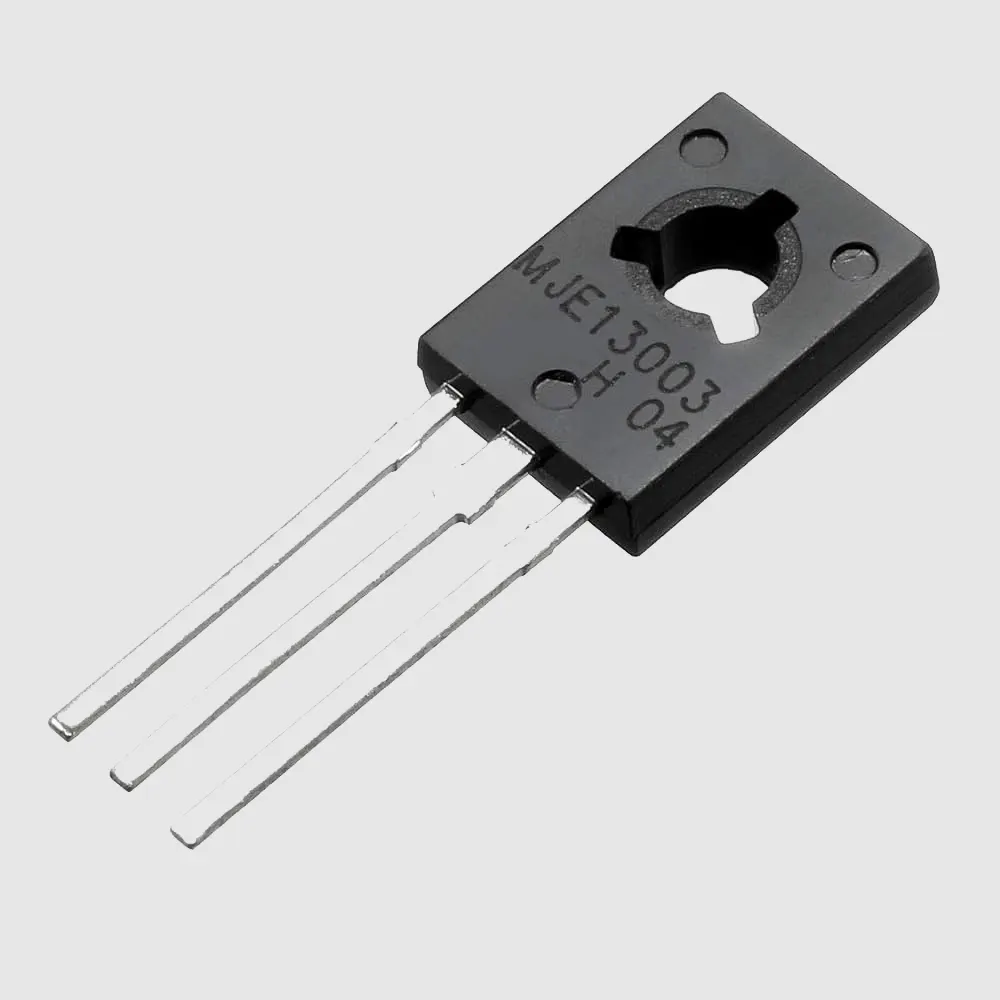
| Package Type | TO-220 |
The mje13003 transistor and its variants, such as the mje13003, deliver reliable high-voltage switching capability in compact designs.
Key Takeaways
-
The 13003 transistor handles high voltage up to 400V and current up to 4A, making it ideal for power switching and control circuits.
-
Its fast switching speed and low saturation voltage improve efficiency in power supplies, inverters, and motor controllers.
-
The TO-220 package and clear pinout (Collector, Base, Emitter) simplify installation and heat management.
-
Using a proper base resistor protects the transistor and ensures reliable switching in electronic circuits.
-
Several equivalent transistors like MJE13003 and KSE13003 offer similar performance for easy replacement without major circuit changes.
13003 Transistor Overview
Main Features
The mje13003 transistor stands as a reliable choice for high-voltage and high-speed switching applications. Engineers value its robust silicon NPN structure, which supports efficient power management in demanding environments. The mje13003 offers a collector-emitter voltage rating up to 600 volts and a collector current capacity reaching 4 amperes. These specifications enable the mje13003 transistor to handle significant power loads without compromising stability.
Key features include:
-
High collector-emitter voltage (up to 600V)
-
Collector current capability up to 4A
-
Fast switching speed (transition frequency around 2 MHz)
-
Low collector-emitter saturation voltage for efficient operation
-
Wide operating temperature range (-65°C to +150°C)
-
Durable TO-220 package for effective heat dissipation
Note: The mje13003 transistor’s fast switching and high voltage tolerance make it ideal for circuits that require rapid and reliable power control.
The following table summarizes the core parameters that validate the mje13003’s effectiveness in industrial applications:
| Parameter | Specification/Range | Application Relevance |
|---|---|---|
| Collector-Emitter Voltage | 400 - 600 V | Handles voltage spikes in switching regulators, inverters, and motor controls |
| Collector Current | 1.5 - 4.0 A | Manages substantial current loads in power circuits |
| Power Dissipation | 25 W | Supports robust operation under high power conditions |
| Transition Frequency | ~2 MHz | Enables high-speed switching for PWM and fast circuits |
Typical Applications
The mje13003 transistor finds widespread use in modern electronics, especially where efficient power conversion and control are essential. Designers often select the mje13003 for switched-mode power supplies (SMPS), inverter circuits, and uninterruptible power supplies (UPS). Its high voltage and current ratings allow the mje13003 transistor to regulate power conversion efficiently, minimizing energy loss and improving system reliability.
In inverter circuits, the mje13003 manages DC to AC conversion, which is vital for renewable energy systems and backup power solutions. Motor controllers also benefit from the mje13003 transistor’s ability to modulate speed and torque with precision, supporting automation and robotics. The mje13003’s moderate base current requirements and balanced current gain ensure rapid switching and effective amplification, making it a preferred component in demanding applications.
Tip: When designing circuits that require both high voltage endurance and fast switching, the mje13003 provides a dependable solution for engineers and hobbyists alike.
Datasheet
Key Specifications
The mje13003 transistor stands out for its robust high-voltage performance and reliable silicon NPN structure. Engineers often consult the mje13003 datasheet to verify the device’s suitability for demanding power switching applications. The datasheet provides a comprehensive overview of the transistor’s technical specifications, which include high collector-emitter voltage, moderate collector current, and efficient power dissipation. These features make the mje13003 a preferred choice in circuits that require both durability and efficiency.
The mje13003 datasheet pdf highlights the following key parameters:
| Parameter | Rating |
|---|---|
| Collector-Emitter Voltage (Vceo) | 400 V |
| Collector-Base Voltage (Vcbo) | 700 V |
| Base-Emitter Voltage (Vbe) | 9 V |
| Maximum Collector Current (Ic) | 1.5 A |
| Maximum Base Current (Ib) | 0.75 A |
| Power Dissipation (Pc) | 40 W |
| Operating Temperature Range | -55 to 150 °C |
| Package Type | TO-220 |
The mje13003’s high collector-emitter voltage rating of 400 volts allows it to withstand significant voltage stress in switching circuits. Its collector-base voltage of 700 volts further enhances its resilience in high-voltage environments. The device’s maximum collector current of 1.5 amperes supports moderate current loads, making it suitable for both switching and amplification tasks. The TO-220 package ensures effective heat dissipation, which is essential for maintaining performance under continuous operation.
Note: The mje13003’s silicon NPN structure provides stable operation and low dynamic parameter spread, ensuring consistent performance across a wide range of operating conditions.
Electrical Ratings
The datasheet pdf for the mje13003 details several critical electrical ratings that define its operational limits. These ratings help engineers determine the safe and optimal conditions for using the transistor in various applications. The mje13003’s technical specifications include a power dissipation capacity of 40 watts, which enables the device to handle substantial energy without overheating. The base-emitter voltage of 9 volts and a base current rating of 0.75 amperes ensure reliable switching action and efficient drive requirements.
The mje13003 datasheet also specifies a DC current gain (hFE) range from 25 to 100, which supports effective amplification and switching. The operating temperature range from -55°C to 150°C allows the mje13003 to function reliably in both industrial and consumer environments. These technical specifications confirm the device’s versatility and robustness.
The following chart visually summarizes the key performance ratings of the mje13003 transistor:
Engineers rely on the datasheet to ensure that the mje13003 operates within its specified limits. The low dynamic parameter spread, as indicated in the datasheet, means that the device maintains consistent characteristics even when subjected to varying electrical stresses. This reliability is crucial for applications such as switching regulators, inverters, and power supply circuits.
When reviewing the mje13003 datasheet pdf, designers can quickly identify the transistor’s strengths in high-voltage and moderate-current scenarios. The datasheet serves as a vital reference for selecting the right component for power electronics projects, ensuring both safety and performance.
13003 Transistor Pinout
Pin Diagram
The mje13003 transistor features a straightforward pinout that simplifies circuit integration. This device uses the TO-220 package, which is common for power transistors. When examining the mje13003, users should always reference the flat side of the casing. Holding the transistor with the flat side facing forward, the pins are arranged from left to right as Collector, Base, and Emitter. This orientation matches the standard configuration for plastic-cased BJTs, making identification consistent across similar components.
The mje13003 pinout follows a serial arrangement. The first pin on the left is the Collector, the middle pin is the Base, and the rightmost pin is the Emitter. This layout allows for quick identification during assembly or troubleshooting. The clear pinout structure reduces the risk of wiring errors, especially in high-voltage applications where accuracy is critical.
Tip: Always double-check the mje13003 pinout before soldering the transistor onto a PCB. Proper orientation ensures reliable operation and prevents circuit faults.
Pin Functions
Each pin on the mje13003 serves a distinct function within electronic circuits. The Collector pin handles the main current flow from the load. The Base pin acts as the control terminal, receiving the input signal that switches the transistor on or off. The Emitter pin provides the path for current to exit the device and return to ground.
-
Collector (Pin 1): Connects to the load or power supply. It manages the majority of the current passing through the mje13003.
-
Base (Pin 2): Receives the control signal. A small current at this pin enables the transistor to switch larger currents between the Collector and Emitter.
-
Emitter (Pin 3): Serves as the output terminal. It completes the circuit by allowing current to flow out of the mje13003 and back to ground.
The mje13003 pinout ensures that each pin performs its role efficiently. Designers rely on this configuration for consistent switching and amplification in power electronics. The standard pinout also aids in replacing the mje13003 with equivalent transistors, as most alternatives use the same pin arrangement.
Note: Understanding the mje13003 pinout is essential for safe and effective circuit design. Proper pin identification prevents damage to the transistor and connected components.
13003 Transistor Applications
Switch Circuit
Engineers often use the mje13003 transistor as a high-speed electronic switch in various control circuits. The device can handle rapid on-off cycles, making it ideal for switching loads such as lamps, relays, or small motors. In a basic switch circuit, the base receives a control signal through a resistor. When the base voltage rises above the threshold, the mje13003 transistor enters saturation mode. Current flows from collector to emitter, activating the connected load.
A simple switch circuit diagram appears below:
 Vcc
  |
 [Load]
  |
Collector
   |
Base --[R]-- Control Signal
   |
Emitter
  |
 GND
This configuration allows the mje13003 to act as an efficient switch. The transistor remains off until the control signal triggers the base. Once activated, it provides a low-resistance path for current, ensuring reliable operation in automation and timing circuits.
Tip: Use a suitable base resistor to limit current and protect the mje13003 transistor from damage.
Power Supply Example
The mje13003 transistor plays a crucial role in switched-mode power supplies (SMPS). In these circuits, the device rapidly switches on and off, converting DC input into high-frequency pulses. These pulses drive a transformer, which steps voltage up or down as needed. The mje13003’s fast switching speed and high voltage tolerance make it well-suited for this application.
A simplified SMPS circuit using the mje13003 appears below:
DC Input
   |
 [Transformer]
   |
Collector
   |
Base --[PWM Controller]
   |
Emitter
  |
 GND
In this setup, a pulse-width modulation (PWM) controller sends signals to the base. The mje13003 transistor switches the transformer primary winding on and off at high frequency. This process enables efficient voltage conversion with minimal energy loss. Many engineers select the mje13003 transistor for power supply designs due to its robust performance and reliability.
Note: The mje13003 applications extend to inverters and motor drivers, where precise and efficient switching is essential.
13003 Transistor Equivalent
Replacement List
Engineers often need suitable alternatives when the original 13003 transistor is unavailable or when they want to optimize circuit performance. Several transistors share similar electrical characteristics and pin configurations with the 13003. These equivalents allow designers to maintain circuit functionality without significant modifications.
Common replacement options include:
-
MJE13003 transistor
-
2N5551
-
2SC2655
-
2SC945
-
BD139
-
KSE13003
Each of these transistors offers comparable voltage and current ratings. The MJE13003 transistor stands out as the most direct substitute due to its matching specifications and TO-220 package. Other alternatives, such as the 2N5551 and BD139, may require minor adjustments in circuit design, especially regarding power dissipation and switching speed.
Note: Always verify the datasheet of the replacement transistor to ensure compatibility with the intended application.
Comparison Table
The following table compares the 13003 transistor with its common equivalents. This comparison helps engineers select the best substitute based on voltage, current, power dissipation, and package type.
| Transistor | Vceo (V) | Ic (A) | Power (W) | Package | Notes |
|---|---|---|---|---|---|
| 13003 | 400 | 1.5 | 40 | TO-220 | Standard reference |
| MJE13003 | 400 | 1.5 | 40 | TO-220 | Direct replacement |
| 2N5551 | 160 | 0.6 | 0.625 | TO-92 | Lower voltage/current |
| 2SC2655 | 400 | 1.5 | 30 | TO-220 | Similar specs |
| BD139 | 80 | 1.5 | 12.5 | TO-126 | Lower voltage |
| KSE13003 | 400 | 1.5 | 40 | TO-220 | Equivalent performance |
This table highlights the importance of matching both electrical and mechanical parameters. The MJE13003 transistor and KSE13003 provide the closest match, ensuring seamless integration into existing designs. Other options may suit less demanding applications or require additional circuit considerations.
The 13003 transistor delivers strong high-voltage performance and reliable switching for power electronics. Engineers benefit from its robust datasheet specifications and straightforward pinout, which simplify circuit integration. Careful review of equivalents ensures compatibility in replacement scenarios. Designers often choose the 13003 for switching regulators, inverters, and motor control projects. Selecting the right transistor supports safe, efficient, and long-lasting circuit operation.
FAQ
What is the maximum voltage the 13003 transistor can handle?
The 13003 transistor supports a maximum collector-emitter voltage of 400V. This high-voltage capability makes it suitable for power supply and inverter circuits.
How can someone test a 13003 transistor with a multimeter?
Set the multimeter to diode mode. Place the positive probe on the base and the negative on the emitter or collector. A reading between 0.6V and 0.7V indicates a functional junction.
Can the 13003 transistor replace a BD139 in circuits?
The 13003 transistor can replace a BD139 only in circuits that require higher voltage ratings. However, users must check current and power requirements before substitution.
What precautions should users take when soldering the 13003 transistor?
-
Use a heat sink to prevent overheating.
-
Avoid prolonged contact with the soldering iron.
-
Double-check the pinout before installation.
Is the 13003 transistor suitable for audio amplification?
The 13003 transistor is not ideal for audio amplification. Its design focuses on switching and power regulation, not low-noise or linear amplification.
Written by Jack from AIChipLink.
AIChipLink, one of the fastest-growing global independent electronic components distributors in the world, offers millions of products from thousands of manufacturers, and many of our in-stock parts is available to ship same day.
We mainly source and distribute integrated circuit (IC) products of brands such as Broadcom, Microchip, Texas Instruments, Infineon, NXP, Analog Devices, Qualcomm, Intel, etc., which are widely used in communication & network, telecom, industrial control, new energy and automotive electronics.
Empowered by AI, Linked to the Future. Get started on AIChipLink.com and submit your RFQ online today!